Multifunctional wireless mobile power supply

A technology of wireless mobile power supply and mobile power supply, which is applied in the direction of current collectors, electric vehicles, electrical components, etc., can solve the problems of shortened service life, waste of traditional energy, and difficulty in heat dissipation, so as to prolong service life, save traditional energy, and avoid burn out effect

Inactive Publication Date: 2018-03-23
CHANGXING SHENGFAN TEXTILE
View PDF0 Cites 3 Cited by
  • Summary
  • Abstract
  • Description
  • Claims
  • Application Information

AI Technical Summary

Problems solved by technology

[0002] People are becoming more and more dependent on smart phones. Since there is no major breakthrough in battery technology, mobile phones need to be charged frequently. In order to meet the needs of outdoor charging, people have invented mobile power. At present, only wired mobile power is available. In the state of outdoor sports, charging is inconvenient. The market needs a wireless mobile power supply that can charge smartphones and smart watches. It can be in different working modes according to the type of electronic products. It is simple to charge and easy to use. With the development of science and technology, there are more and more wireless mobile power supplies, and their functions are becoming more and more powerful. Among them, there are many multi-functional wireless mobile power supplies.
[0003] However, most of the existing wireless mobile power supplies have single functions and complex charging, which leads to poor applicability, and is not easy to dissipate heat, resulting in a shorter overall service life, and cannot use new energy sources such as solar energy, resulting in a waste of too much traditional energy.

Method used


Image

  • Multifunctional wireless mobile power supply
  • Multifunctional wireless mobile power supply
  • Multifunctional wireless mobile power supply

Examples


Embodiment Construction

[0019] The following will clearly and completely describe the technical solutions in the embodiments of the present invention with reference to the accompanying drawings in the embodiments of the present invention. Obviously, the described embodiments are only some, not all, embodiments of the present invention. Based on the embodiments of the present invention, all other embodiments obtained by persons of ordinary skill in the art without making creative efforts belong to the protection scope of the present invention.

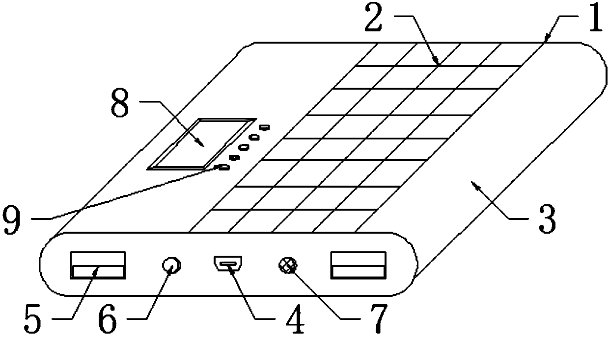
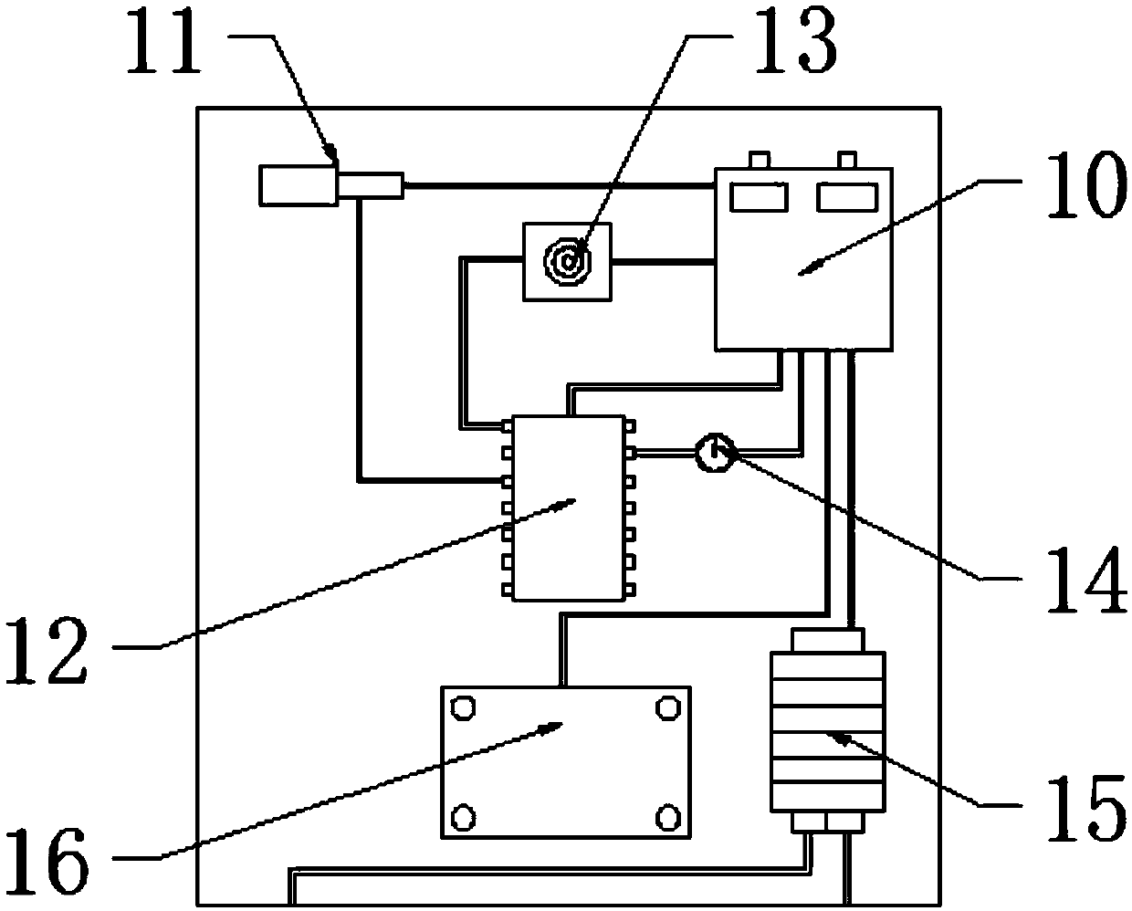
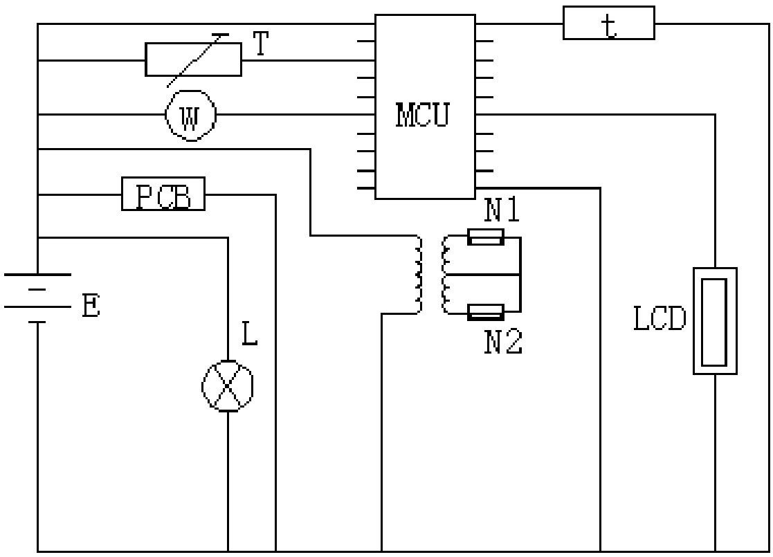
[0020] see Figure 1-3 , the present invention provides a technical solution: a multifunctional wireless mobile power supply, including a mobile power supply main body 1, the mobile power supply main body 1 is composed of a solar battery panel 2 arranged on the top of the mobile power supply main body 1 and a solar battery panel 2 arranged at the bottom The power box 3 constitutes, and the solar cell panel 2 is embedded in the power box 3;

[0021] The side o...


PUM


Abstract

The invention discloses a multifunctional wireless mobile power supply, and the power supply comprises a mobile power supply main body. The mobile power supply main body consists of a solar cell paneldisposed at the top of the mobile power supply main body, and a power box disposed at the bottom of the solar cell panel. The power supply provides two voltages (5V and 9V) through a three-end outputmode of a transformer, so the power supply can be used for charging various types of electronic products, and is very high in applicability. The power supply also can be connected with a printed circuit board through a Bluetooth, so as to achieve the wireless charging. Meanwhile, an MFT temperature sensor is used for measuring the temperature of the storage battery in real time, and transmittingthe temperature to a DSPS (digital signal processing chip). When an overheating phenomenon appears, a heat radiator is controlled to be started for effective heat radiation, thereby preventing the storage battery from being damaged by overheating, and prolonging the service life of the storage battery. Moreover, the solar cell panel can be used for absorbing the solar radiation for power generation, thereby greatly saving the conventional resources, and causing no pollution to the environment.

Description

technical field [0001] The invention relates to the technical field of mobile power supplies, in particular to a multifunctional wireless mobile power supply. Background technique [0002] People are becoming more and more dependent on smart phones. Since there is no major breakthrough in battery technology, mobile phones need to be charged frequently. In order to meet the needs of outdoor charging, people have invented mobile power. At present, only wired mobile power is available. In the state of outdoor sports, charging is inconvenient. The market needs a wireless mobile power supply that can charge smartphones and smart watches. It can be in different working modes according to the type of electronic products. It is simple to charge and easy to use. With the development of science and technology, there are more and more wireless mobile power supplies, and their functions are becoming more and more powerful. Among them, there are many multi-functional wireless mobile powe...

Claims


Application Information

Patent Timeline
IPC IPC(8): H02J7/00H02J7/35H02J50/20H05K7/20
CPCH02J7/00H02J7/0042H02J7/0068H02J7/35H02J50/20H05K7/2089
Inventor 豆树华
Owner CHANGXING SHENGFAN TEXTILE
Why Eureka
Try Eureka