
Fluidized-bed combustion device

A technology of combustion device and fluidized bed, which is applied in the direction of fluidized bed combustion equipment, burning fuel in molten state, combustion method, etc. It can solve the problems of short operation period and difficulty in slag discharge of garbage furnace, and achieve the improvement of fluidization condition, Good economic benefits, reducing the number of shutdowns

Active Publication Date: 2018-03-27
QINGDAO UNIV +1
View PDF8 Cites 0 Cited by
  • Summary
  • Abstract
  • Description
  • Claims
  • Application Information

AI Technical Summary

Problems solved by technology

Due to the large size of bricks and cement blocks, it is difficult to discharge slag from the garbage furnace and the operation period is short

Method used


Image

  • Fluidized-bed combustion device
  • Fluidized-bed combustion device
  • Fluidized-bed combustion device

Examples


Embodiment 1

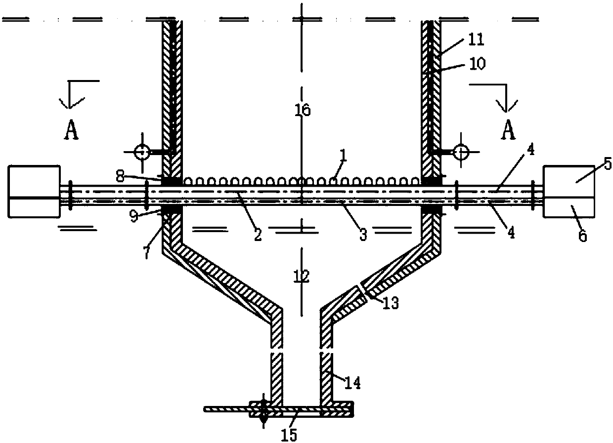
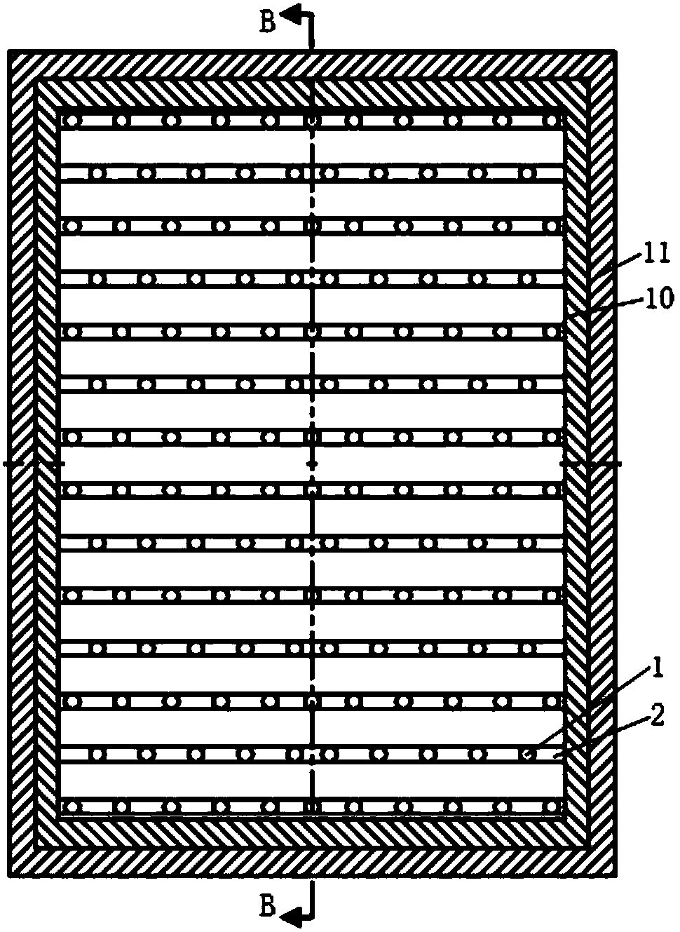
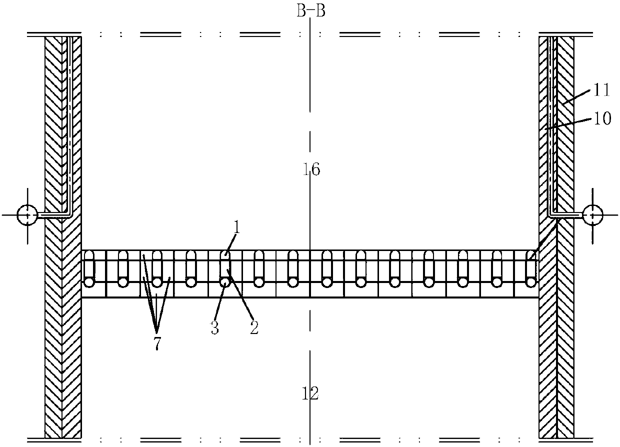
[0025] The main structure of the fluidized bed combustion device involved in this embodiment includes a wind cap 1, an air distribution pipe 2, a cooling air pipe 3, a metal hose 4, an upper air chamber 5, a lower air chamber 6, a movable block brick assembly 7, and thermal insulation cotton 8 , detachable cover plate 9, furnace 16, slag hopper 12, slag discharge pipe 14 and slag discharge door 15, wherein, furnace 16 comprises furnace inner wall 10 and furnace outer wall 11, and the bottom of furnace 16 of columnar and cavity structure is vertically arranged A funnel-shaped slag hopper 12 is provided, and more than one slag hopper small hole 13 is provided on the slope of the slag hopper 12. The lower part of the slag hopper 12 is vertically provided with a slag discharge pipe 14, and the bottom of the slag discharge pipe 14 is provided with a slag discharge door. 15. There are more than three rows of air distribution pipes 2 horizontally below the inner wall 10 of the furnace...

Embodiment 2

[0036] The difference between this embodiment and Embodiment 1 is that the movable block brick assembly is a strip-shaped top movable block brick, two strip-shaped side movable block bricks with the same size and symmetrical structure and a U-shaped bottom The back-type integrated structure composed of movable block bricks reduces the number of components of the movable block brick assembly of a large-scale combustion device, and is convenient for practical application.

[0037] The specific steps of air distribution and slag discharge of the fluidized bed combustion device involved in this embodiment are different from those of Embodiment 1 in that: when adjusting the size of slag discharge in step (4), the single movable block brick assembly 7 is pulled out as a whole .

Embodiment 3

[0039] The difference between this embodiment and Embodiment 2 is that the movable block brick assembly of the integrated structure can be split into a combined structure according to the axis of symmetry or diagonal, according to the use for fluidized bed waste incineration and garbage The type of fuel incinerated in the field of power generation technology and the processing capacity of the combustion device select the corresponding movable block brick assembly, which is convenient for operation and application.

[0040] The specific steps of air distribution and slag discharge of the fluidized bed combustion device involved in this embodiment are the same as those in Embodiment 1.


PUM


Abstract

The invention belongs to the technical field of boiler equipment and relates to a fluidized-bed combustion device. The fluidized-bed combustion device is applied to the technical occasions of fluidized-bed garbage incineration and garbage power generation; the three technical problems that the slagging operation is difficult, the running cycle is short, and the concentration of CO in flue gas is high can be solved; the urban environmental pollution can be effectively reduced; and the service life of a combustion device can be prolonged. The main structure of the fluidized-bed combustion devicecomprises air caps, air distribution pipes, cooling air pipes, metal hoses, upper air chambers, lower air chamber, movable block bricks, heat preservation cotton, detachable cover plates and a furnace hearth, wherein the air caps are arranged at the tops of the air distribution pipes; the upper air chambers and the lower air chambers are symmetrically arranged on the outer wall of the furnace hearth, and correspondingly communicate with the air distribution pipes and the cooling air pipes through the metal hoses; the movable block bricks are embedded in the furnace hearth; the heat preservation cotton is arranged outside the movable block bricks; and the detachable cover plates are arranged outside the heat preservation cotton. The fluidized-bed combustion device is simple in overall structure, reliable in principle, energy-saving, environmentally friendly, long in service, simple and convenient to operate, shorter in handling time, great in economic benefit, and broad in market prospect.

Description

Technical field: [0001] The invention belongs to the technical field of boiler equipment, and relates to a fluidized bed combustion device, which is used in the technical fields of fluidized bed garbage incineration and garbage power generation. Background technique: [0002] The fluidized bed waste incineration boiler mainly burns waste with high ash content and high moisture content. Due to differences in seasons and geographical locations, the composition of garbage varies greatly in different seasons and regions. For example, in summer, there are more watermelon rinds in the garbage; and in the rainy season, the garbage has more moisture. In Qingdao, there are more beer bottles and bottle caps in the garbage; when there are more construction sites in the city, there will be more cement blocks and bricks. On the other hand, due to the immaturity of garbage sorting and crushing technology, the garbage calorific value is low and the garbage size is relatively large. If t...

Claims


Application Information

Patent Timeline
IPC IPC(8): F23C10/20F23C10/24F23C10/30
CPCF23C10/20F23C10/24F23C10/30F23C2206/10
Inventor 姜华伟吕俊复蒋文斌王翠苹
Owner QINGDAO UNIV
Learn More