Self-injection locking resonant optical gyroscope and working method thereof

A technology of self-injection locking and optical gyroscope, which is applied in the field of self-injection locking resonant optical gyroscope, can solve the problems of increasing non-reciprocal noise, complex gyroscope structure, reducing gyroscope sensing accuracy and working stability, etc., to avoid non-reciprocal The effects of easy noise, simple structure symmetry, and simplified structure and working methods

Active Publication Date: 2018-03-27
CHANGCHUN UNIV OF SCI & TECH
View PDF5 Cites 11 Cited by
  • Summary
  • Abstract
  • Description
  • Claims
  • Application Information

AI Technical Summary

Problems solved by technology

However, this solution requires the use of a ring cavity with gain, which belongs to the laser gyro and works in an active manner. It requires two pump lasers and a seed laser, and the structure of the gyro is relatively complicated; in addition, compared to the gyro using

Method used


Image

  • Self-injection locking resonant optical gyroscope and working method thereof
  • Self-injection locking resonant optical gyroscope and working method thereof

Examples


Embodiment Construction

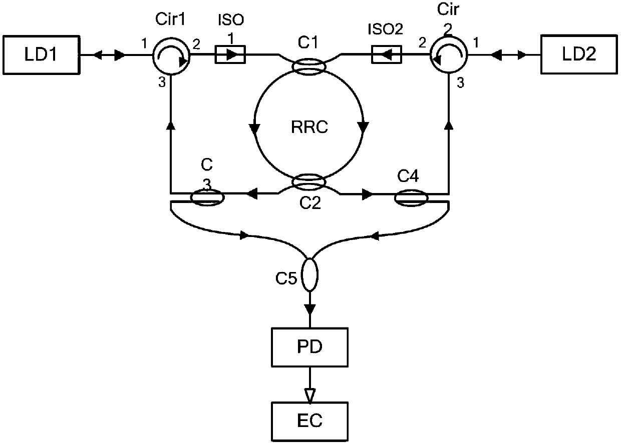
[0016] The self-injection locked resonant optical gyroscope of the present invention is as figure 2 As shown, the left working light source LD1 is connected to a port 1 of the left circulator Cir1 by an optical fiber, and the left circulator Cir1 is a clockwise circulator; the left circulator Cir1, input coupler C1, passive ring resonant cavity RRC, output coupler C2, the left splitter coupler C3, and the left circulator Cir1 are sequentially connected to form the outer resonant circuit of the left working light source LD1, and the ring resonance direction is clockwise, wherein the next port 2 of the left circulator Cir1 is connected to the input coupler C1, The left beam-splitting coupler C3 is connected to the next port 3 of the left circulator Cir1; the left isolator ISO1 is set along the resonance direction in the outer resonant circuit of the left working light source LD1; the right working light source LD2 is connected to the right circulator Cir2 by optical fiber One p...


PUM


Abstract

The invention discloses a self-injection locking resonant optical gyroscope and a working method thereof and belongs to the technical field of optical gyroscopes. The existing resonant optical gyroscope is complex in structure and work. LD is used as a working light source so that the size of the optical gyroscope is reduced. The two LD working light sources share a passive ring resonator so thatnon-reciprocity noise is avoided. Compared with the existing resonant optical gyroscope, the self-injection locking resonant optical gyroscope mainly comprises conventional circuit elements such as circulators, isolators, couplers and resonators in the field of optical fiber technology and has a symmetrical and simple structure. The self-injection locking frequency stabilization method is free ofa modulated signal generator and power-based frequency stabilization. Lights transmitted by the two working light sources carry out resonance along opposite directions in the same passive ring resonator, and two resonance light beams transmitted along different directions are divided through a splitting coupler and are respectively used for frequency stabilization and gyro signal detection. The optical gyroscope has a simple structure and works in a simple work mode.

Description

technical field [0001] The invention relates to a self-injection locking resonant optical gyroscope and a working method thereof, belonging to the technical field of optical gyroscopes. Background technique [0002] The gyroscope is the angular velocity sensor of the carrier and the core component of the inertial navigation, inertial guidance and inertial measurement system. The outstanding advantage of optical gyroscopes is that they have no moving parts. Among them, the technologies of laser gyroscopes and interferometric fiber optic gyroscopes are relatively mature, and because of their high precision, they have a dominant position in the field of high-end gyroscopes. However, these two optical gyroscopes still have their shortcomings, such as large size and high price, which make them unable to meet the requirements of small size, light weight, and low cost for gyroscopes such as microsatellites, tactical missiles, car navigation, robots, and smart phones. . [0003] R...

Claims


Application Information

Patent Timeline
IPC IPC(8): G01C19/72
CPCG01C19/721
Inventor 孔梅张荣
Owner CHANGCHUN UNIV OF SCI & TECH
Why Eureka
Try Eureka