No-wavefront-detection adaptive optical system based on real-time phase difference technology

A technology of adaptive optics and wavefront detection, applied in the field of optics, can solve the problems of small convergence speed calculation, complex implementation methods, slow convergence speed, etc.

Pending Publication Date: 2018-03-27
CHANGCHUN UNIV OF SCI & TECH
View PDF12 Cites 23 Cited by
  • Summary
  • Abstract
  • Description
  • Claims
  • Application Information

AI Technical Summary

Problems solved by technology

[0004] The present invention aims at the problems of slow convergence speed, inability to meet real-time requirements and complex implementation means of current wavefront-free adaptive optics technology, and provides a novel wavefront-free adaptive optics system based on real-time phase difference technology, which has a simple structure , High light energy utilization rate, fast convergence speed, small amount of calculation, no need to define basis functions or calibration in advance, simple implementation methods, etc.

Method used


Image

  • No-wavefront-detection adaptive optical system based on real-time phase difference technology
  • No-wavefront-detection adaptive optical system based on real-time phase difference technology
  • No-wavefront-detection adaptive optical system based on real-time phase difference technology

Examples


Embodiment Construction

[0070] The present invention will be described in further detail below in conjunction with the accompanying drawings.

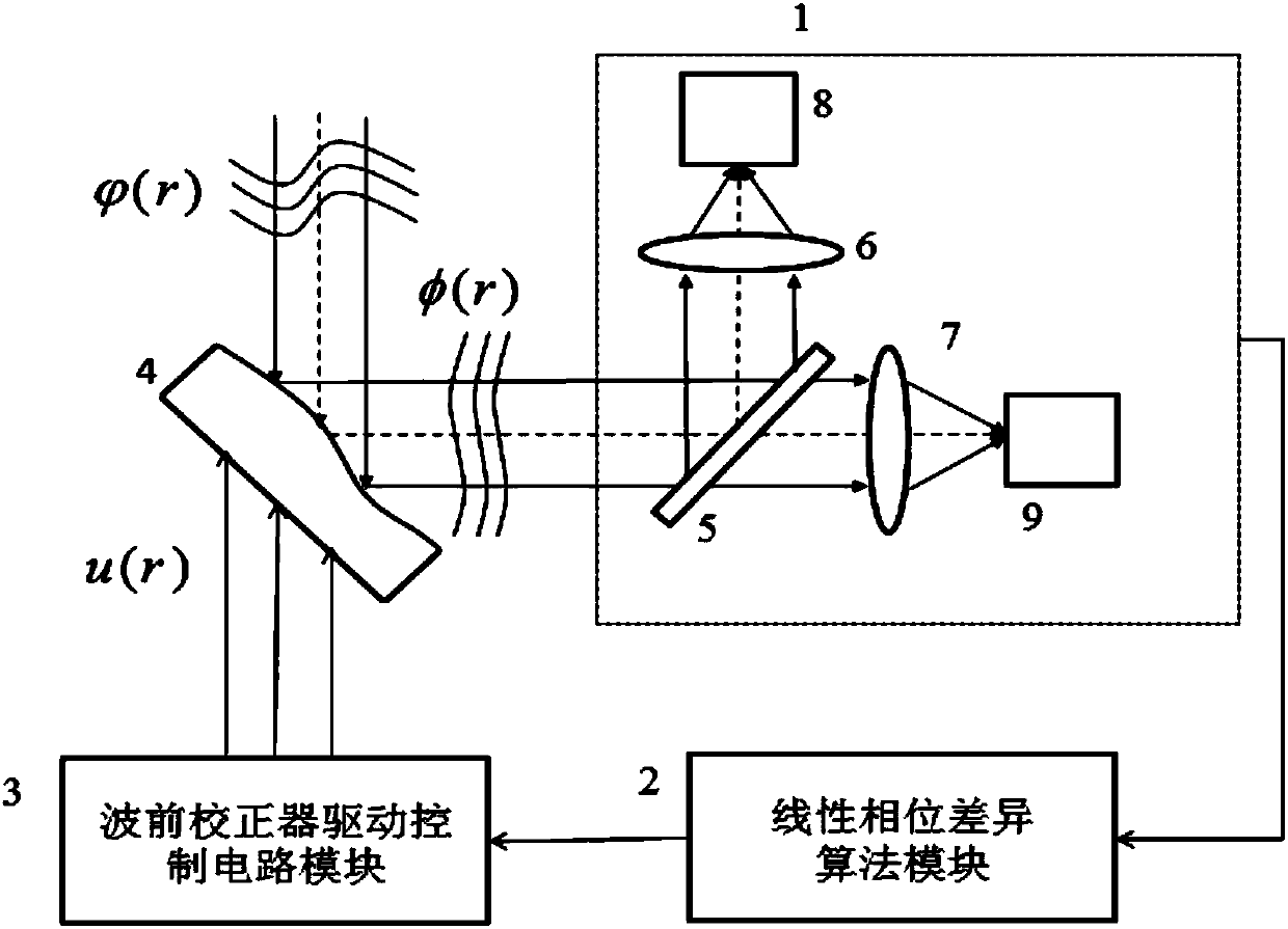
[0071] Such as image 3 As shown, the adaptive optics system without wavefront detection based on real-time phase difference technology consists of an imaging system 1, a linear phase difference algorithm module 2, a wavefront corrector drive control circuit module 3, and a deformable mirror 4, wherein the imaging system 1 consists of a spectroscopic Prism 5, imaging lens 1 6, imaging lens 2 7, CCD camera 1 8 and CCD camera 2 9 are used to perform in-focus and out-of-focus exposure on the light spot respectively. When the adaptive optics system is working, the residual wavefront after the wavefront aberration to be corrected is compensated by the deformable mirror 4 is incident on the beam splitting prism 5, and is divided into two beams of light by the beam splitting prism 5, which are respectively imaged by the imaging lens-6 and the beam-splitting prism. ...


PUM


Abstract

The invention discloses a no-wavefront-detection adaptive optical system based on the real-time phase difference technology, belongs to the technical field of optics, and aims at problems of the conventional no-wavefront-detection adaptive optical technology. The system employs a method which comprises the steps: enabling the residual wavefront of to-be-corrected wavefront aberration after compensation through a deformation mirror to be transmitted to a beam splitter prism, dividing the residual wavefront into two beams through the beam splitter prism, converging the two beams to two CCD cameras through two imaging lenses, and obtaining focal plane and defocus plane fuzzy image patches; taking the image information as a known input quantity, directly solving a corresponding drive control voltage through a linear phase different algorithm module, driving a control circuit module to be applied to a deformation mirror through a wavefront corrector, and enabling the deformation mirror to generate a compensation quantity without wavefront distortion; collecting the focal plane and defocus plane images corresponding to the corrected system through an imaging system, recalculating a corresponding correction voltage at this moment, and carrying out the iteration of the above operations till the wavefront error is completely corrected. The system is used on an adaptive optical closed-loop system.

Description

technical field [0001] The invention belongs to the field of optical technology, and relates to a novel adaptive optical system, in particular to an adaptive optical system without wavefront detection based on real-time phase difference technology. Background technique [0002] The establishment and development of adaptive optics theory first originated in astronomy, and its application in astronomical observation has always been the main application direction of this technology. The adaptive optics system usually uses a wavefront sensor to detect the phase information of the distorted wavefront, and uses a wavefront corrector to correct the distorted wavefront, such as figure 1 shown. Due to the fast speed and high precision of the Shack-Hartmann wavefront sensor, it is widely used in the adaptive optics system with high real-time requirements. However, with the expansion of the application field of adaptive optics technology, such as free-space optical communication, ext...

Claims


Application Information

Patent Timeline
Patent Type & Authority Applications(China)
IPC IPC(8): G02B26/06G02B27/00
CPCG02B26/06G02B27/0025
Inventor 岳丹聂海涛高旭李野母一宁司英男陈雪微
Owner CHANGCHUN UNIV OF SCI & TECH
Why Eureka
Try Eureka