Jack connector assembly

A technology of connectors and contacts, which is applied to the parts, connections, electrical components of connecting devices, etc., can solve the problems of difficulty in adjusting the size of the plugging force, increased stress relaxation of materials, and high heat generation of contacts, so as to reduce the heat. , the effect of enhancing electrical conductivity and improving electrical conductivity

Pending Publication Date: 2018-03-27
SHENZHEN QILIAN TECH CO LTD
View PDF0 Cites 4 Cited by
  • Summary
  • Abstract
  • Description
  • Claims
  • Application Information

AI Technical Summary

Problems solved by technology

Therefore, it is usually necessary to choose a contact material with good comprehensive performance, such as beryllium copper, but this material is expensive, mainly imported, and the delivery time is as long as several months
And there are also many deficiencies in the beryllium copper material of the prior art, for example: the electrical conductivity of beryllium copper (%IACS) is between 17%~65%, and there is still a big difference between the 100% electrical conductivity of pure copper, re

Method used


Image

  • Jack connector assembly
  • Jack connector assembly
  • Jack connector assembly

Examples


no. 1 approach

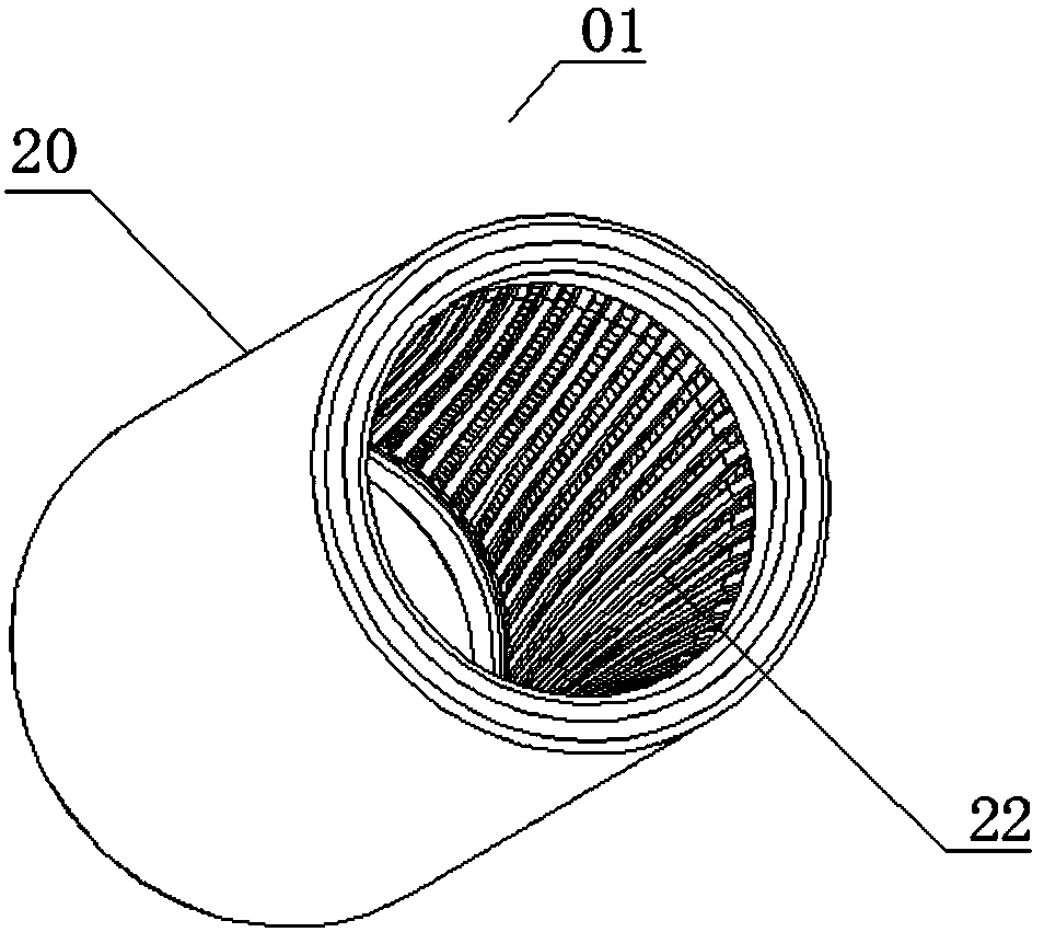
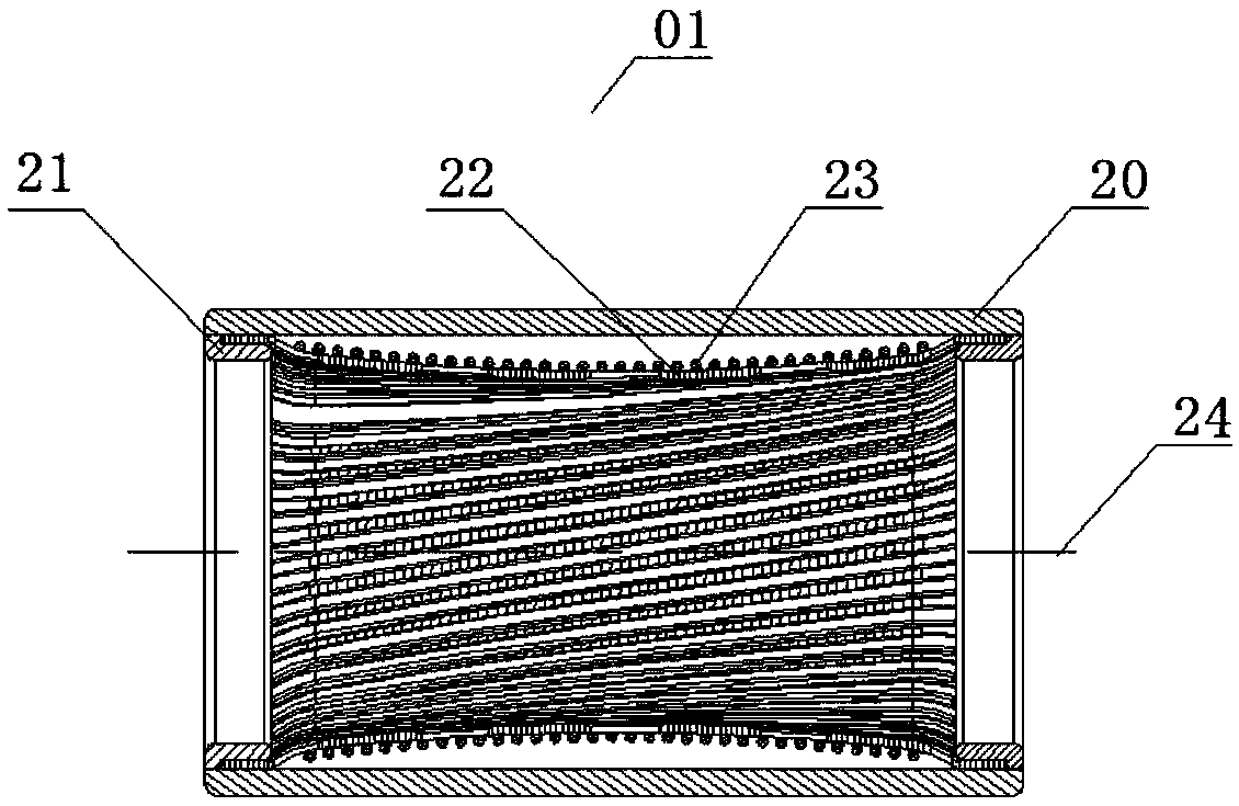
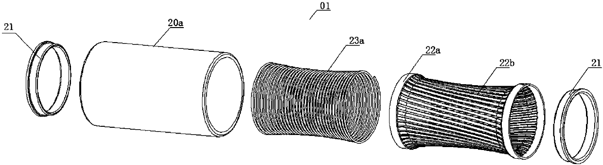
[0081] Figure 1a A perspective view of the jack connector according to the first embodiment of the present application is shown. Figure 1b A sectional view along the axis of the receptacle connector according to the first embodiment of the present application is shown. Figure 1c An exploded view of the jack connector according to the first embodiment of the present application is shown. Figure 1d A perspective view of the contact and the pressure part according to the first embodiment of the present application is shown.

[0082] Such as Figure 1a , 1b , 1c and 1d, the receptacle connector 01 according to the first embodiment of the present application includes a receptacle sleeve 20, two inner ferrules 21, a cage type cylindrical contact 22 and a pressure part 23. The socket sleeve 20 further includes a cylindrical contact sleeve 20a. The cage-type cylindrical contact piece 22 is a single-section leaf spring, including two ring-shaped fixed contact parts 22a that are ...

no. 2 approach

[0089] Figure 2a It shows an exploded view of the jack connector related to the second embodiment of the present application, Figure 2b A perspective view of a contact and a pressure portion according to a second embodiment of the present application is shown. Figure 2c A perspective view of the O-ring silicone elastomer according to the second embodiment of the present application is shown.

[0090] Such as Figure 2a and 2b As shown, the second embodiment of the present application is a deformation of the first embodiment, the difference is that the pressure part 234 of the connector 02 is realized as an elastic body formed of a polymer material, and the pressure part 234 in this embodiment is a silicone elastic body 234a . Such as Figure 2aAs shown, the silicone elastic body 234a is a circular cylindrical body, and other elastic structures known to those skilled in the art may also be used, such as an O-ring (O-Ring), as shown in FIG. 2C . The pressure part 234 ca...

no. 3 approach

[0092] Figure 3a A perspective view of a jack connector according to a third embodiment of the present application is shown. Figure 3b A sectional view along the axis of the receptacle connector according to the third embodiment of the present application is shown. Figure 3c An exploded view of the jack connector according to the third embodiment of the present application is shown. Figure 3d A perspective view of a contact and a pressure portion according to a third embodiment of the present application is shown.

[0093] Such as Figure 3a , 3b , 3c and 3d, the third embodiment of the present application is a modification of the first embodiment, the difference is that the pressure part 235 of the connector 03 is implemented as a pressure bag structure, which includes a fluid inlet 235a, a fluid outlet 235b and a cavity 235c. The fluid filled in the cavity is gas or liquid. At the same time, the socket sleeve 201 also leaves gaps at corresponding positions of the f...


PUM


Abstract

The invention provides a jack connector assembly, and the connector assembly comprises a jack sleeve which comprises a cylindrical contact sleeve; a round-cage-type cylindrical contact part which is made of a high-conductivity material, is installed in the cylindrical contact sleeve, is of a line spring or leaf spring structure, and comprises a fixed contact part in electrical connection with thecylindrical contact sleeve, and a separable contact part which is separated with or makes contact with a pin; and a pressure part which is corresponding to the separable contact part, wraps the separable contact part, is installed between the round-cage-type cylindrical contact part and the cylindrical contact sleeve, and provides an external pressure when the pin makes contact with the round-cage-type cylindrical contact part. The round-cage-type cylindrical contact part and the cylindrical contact sleeve are connected electrically to form a current channel, and the pressure part wrapping theexterior is used for providing the external pressure, thereby enabling the round-cage-type cylindrical contact part to give partial consideration or no consideration to a function of providing an elastic force, and to select the high-conductivity material. The conductivity of the line spring or leaf spring contact part is improved, and the dedicated pressure part is used for providing the required external pressure.

Description

technical field [0001] The present application relates to electrical connectors, in particular to a socket connector. Background technique [0002] In the field of electrical connection, there is a type of circular pin socket connector, and the pins are often not directly in hard contact with the inner hole of the jack, but contacts are installed in the inner hole of the jack. The contact piece is a kind of elastic structure, and the pin presses the contact piece when mating, so as to generate a long-term contact force between the pin and the inner hole wall of the socket, so as to ensure the durability of the electrical connection between the pin and the socket and reliability. [0003] Among the contacts, there is a type of wire spring wire (that is, a metal wire with better elasticity). The socket that uses the wire spring wire as the contact is called a wire spring socket, and its full name is a single-leaf rotary hyperboloid wire spring socket. , because of its small ...

Claims


Application Information

Patent Timeline
IPC IPC(8): H01R13/187
CPCH01R13/187
Inventor 马远锋
Owner SHENZHEN QILIAN TECH CO LTD
Why Eureka
Try Eureka