
Steel pipe machining system with automatic coding function

一种加工系统、自动打码的技术,应用在金属加工、制造工具、其他制造设备/工具等方向,能够解决不能解决打码、传输、加工过程描述等问题,达到冷却效果好、便于调整、减少热应力的效果

Active Publication Date: 2018-03-30
ANHUI SHUNXIN PRECISION TUBE MFG CO LTD
View PDF7 Cites 2 Cited by
  • Summary
  • Abstract
  • Description
  • Claims
  • Application Information

AI Technical Summary

Problems solved by technology

[0007] The above applications do not describe the entire processing process, and cannot solve the problems in coding and transmission, and the entire system needs to be improved and designed accordingly

Method used


Image

  • Steel pipe machining system with automatic coding function
  • Steel pipe machining system with automatic coding function
  • Steel pipe machining system with automatic coding function

Examples


Embodiment 1

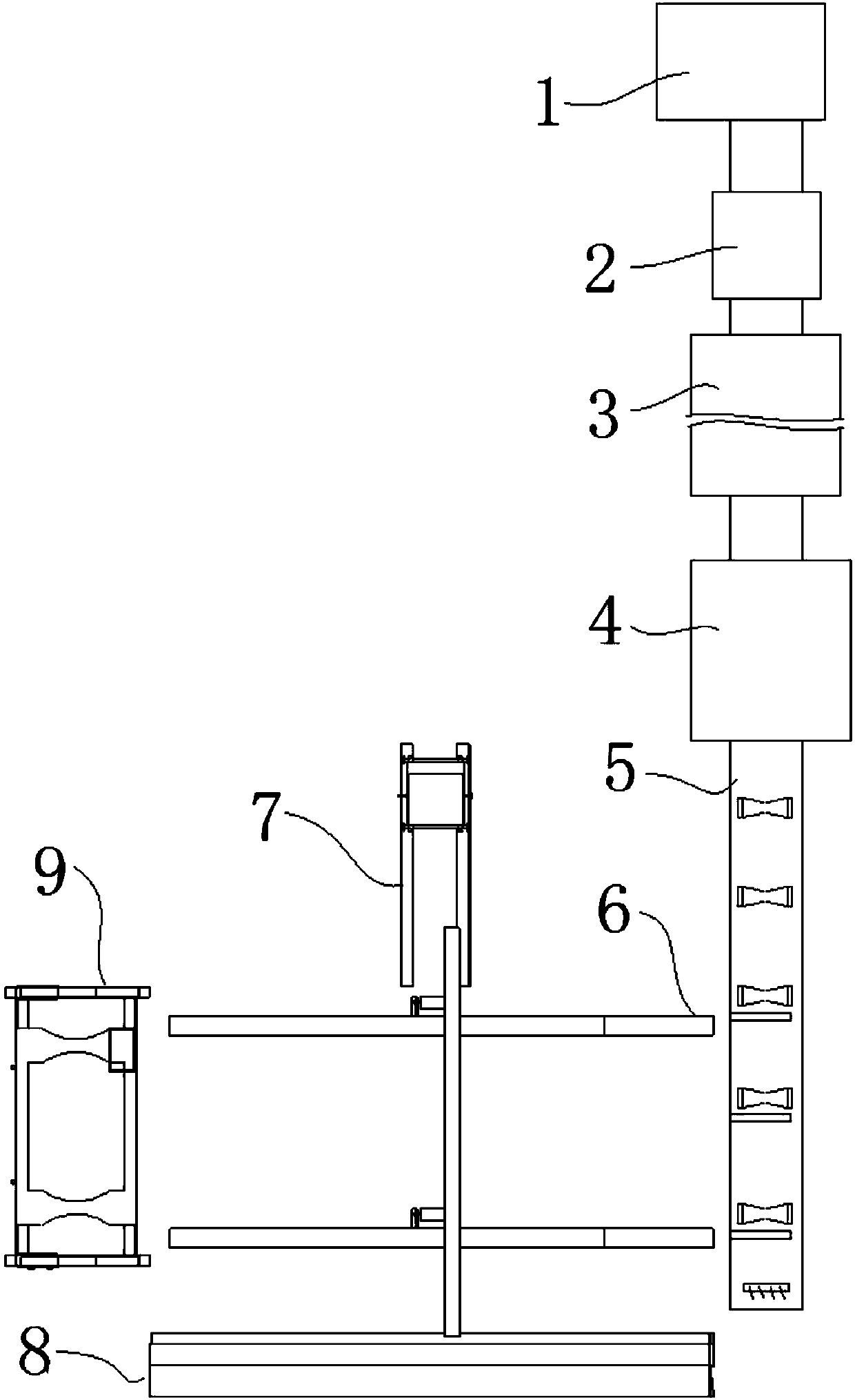
[0049] combine figure 1 , a steel pipe processing system that can automatically code in this embodiment includes an unwinding mechanism 1, a welding mechanism 3, a cutting mechanism 4, a transmission mechanism 5, a coding mechanism 2, an unloading mechanism 6, a chamfering mechanism 7 and Transporter 9, wherein unwinding mechanism 1, roll welding mechanism 3 and cutting mechanism 4 can adopt conventional design. The unwinding mechanism 1 flattens the coiled sheet and sends it to the rolling and welding mechanism 3 after being coded by the coding mechanism 2. The welded steel pipe is cut into a fixed length by the cutting mechanism 4 and enters the transmission mechanism 5. The unloading mechanism 6 Cooperate with the transmission mechanism 5, and set a chamfering mechanism 7 on one side of the unloading mechanism 6, and set a transport vehicle 9 at the tail end of the unloading mechanism 6, and bundle and transport the steel pipes on the transport vehicle 9 after chamfering. ...

Embodiment 2

[0062] to combine Figure 11 , a steel pipe processing system that can automatically print codes in this embodiment, its basic structure is the same as that of Embodiment 1, the difference is that the drainage tank 8 in this embodiment is mainly composed of a water tank bottom plate 801, a left baffle plate 802 and Right baffle plate 803 is formed, and described left baffle plate 802 and right baffle plate 803 are inclined to the both sides of sink bottom plate 801 respectively, and left baffle plate 802 height is less than right baffle plate 803 height; The angle and direction of inclination are the same as those of the right support frame 602 respectively, and the high position end of the drainage groove 8 is in a closed state. The right baffle plate 803 is higher to prevent the outflowing water from splashing out, and the tank bottom plate 801 provided with an inclination makes the cooling water flow to the lower end automatically, and can be recycled after entering the fil...

Embodiment 3

[0065] A steel pipe processing system that can automatically print codes in this embodiment has the same basic structure as that of Embodiment 2, the difference being that a fixed block 6032 is arranged on the horizontal plate of the right-angle support plate 6031 in this embodiment, and the transmission The roller connecting rod 6034 is provided with a threaded hole, and a supporting bolt 6033 is threaded in the threaded hole, and the lower end of the supporting bolt 6033 is inserted into the round hole in the middle of the fixing block 6032 . This structural design facilitates the adjustment of the height of the steel pipe, cooperates with the chamfering mechanism 7, and is suitable for chamfering processing of steel pipes with different pipe diameters.

[0066] In the present invention, various mechanisms cooperate with each other to form a complete steel pipe processing system, which has better effects on coding, engraving and cooling treatment of steel pipes, and the trans...


PUM


Abstract

The invention discloses a steel pipe machining system with the automatic coding function, and belongs to the field of steel pipe machining. The system comprises an unwinding mechanism, a winded welding mechanism, a cutting mechanism, a transmission mechanism, a coding mechanism, a discharging mechanism, a chamfering mechanism and a transport vehicle; the unwinding mechanism enables a rolled boardto be flatly spread, the board is coded through the coding mechanism, and then the board is conveyed to the winded welding mechanism, after welding, the steel pipes are cut into the fixed length through the cutting mechanism, and then the board enters the transmission mechanism, the discharging mechanism is matched with the transmission mechanism, the chamfering mechanism is arranged on one side of the discharging mechanism, the transport vehicle is arranged at the tail end of the discharging mechanism, and after being chamfered, steel pipes are bundled and transported on the transport vehicle. According to the machining system, machining is achieved, coding, cooling, oil removal, discharging, water filtering and other processes can be automatically carried out, coding lettering and cooling of the steel pipe are well carried out, the conveying and transport mechanism is tight in linkage, and the machining quality and the machining efficiency of the steel pipes are greatly improved.

Description

[0001] The patent application of the present invention is a divisional application with the application number: 201510884894X. The filing date of the original application is: 2015 / 11 / 30. The name of the invention is: a steel pipe processing system and processing method that can automatically code. technical field [0002] The invention relates to the technical field of steel pipe processing, and more specifically relates to a steel pipe processing system capable of automatic coding. Background technique [0003] Precision steel pipe is a high-precision steel pipe material processed by cold drawing or hot rolling. Due to the advantages of no oxide layer on the inner and outer walls of precision steel pipes, no leakage under high pressure, high precision, high smoothness, no deformation in cold bending, flaring, and no cracks in flattening, it is mainly used to produce pneumatic or hydraulic components, such as cylinders, Oil cylinders, compression cylinders, liquid storage ma...

Claims


Application Information

Patent Timeline
Patent Type & Authority Applications(China)
IPC IPC(8): B23P23/04B23Q7/05
CPCB23P23/04B23Q7/05
Inventor 张哨兵
Owner ANHUI SHUNXIN PRECISION TUBE MFG CO LTD
Learn More