
Tunnel seepage detection robot based on multi-sensor fusion

A technology of multi-sensor fusion and robotics, applied in the testing of fluid tightness, testing of machine/structural components, and detecting the appearance of fluid at leakage points, etc., can solve the secondary damage of tunnels, increase the burden on workers, and make detection impossible problems, to achieve the effect of liberating labor, high degree of automation, and ensuring detection accuracy and detection efficiency

Active Publication Date: 2018-03-30
HUAZHONG UNIV OF SCI & TECH
View PDF11 Cites 10 Cited by
  • Summary
  • Abstract
  • Description
  • Claims
  • Application Information

AI Technical Summary

Problems solved by technology

Most of the existing water leakage detection uses manual inspection, which is time-consuming and laborious, and it needs to avoid the operating hours of railway locomotives, which makes workers shift shifts and increases the burden on workers
Some automation technologies, such as technology based on temperature gradient / conductivity, radar wave detection technology, infrared thermal imaging detection technology, pulse echo detection technology, etc., technology based on temperature gradient / conductivity need to lay sensor arrays in the entire tunnel, which belongs to Destructive testing will cause secondary damage to the tunnel, and at the same time cost a lot of money. In addition, each of the huge number of seams in the tunnel body may be a potential source of leakage. It is impossible for the sensor array to detect the precise location of all leakage points. ;Radar wave, infrared thermal imaging, pulse thermal imaging, and pulse echo technology need a cart to carry, so it is necessary to avoid the practice of train operation, which is also a burden to the operator, and leads to low detection efficiency

Method used


Image

  • Tunnel seepage detection robot based on multi-sensor fusion
  • Tunnel seepage detection robot based on multi-sensor fusion
  • Tunnel seepage detection robot based on multi-sensor fusion

Examples


Embodiment Construction

[0032]In order to make the object, technical solution and advantages of the present invention clearer, the present invention will be further described in detail below in conjunction with the accompanying drawings and embodiments. It should be understood that the specific embodiments described here are only used to explain the present invention, not to limit the present invention. In addition, the technical features involved in the various embodiments of the present invention described below can be combined with each other as long as they do not constitute a conflict with each other.

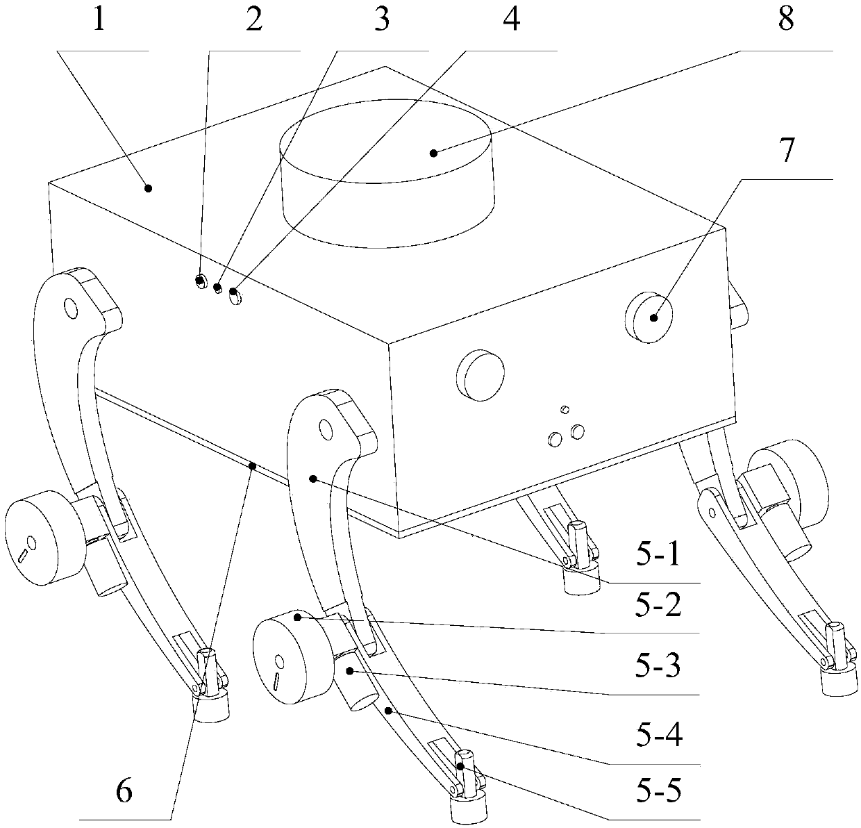
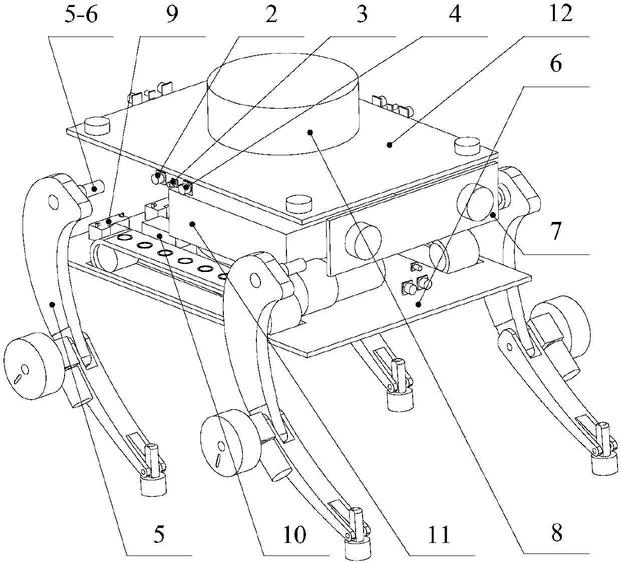
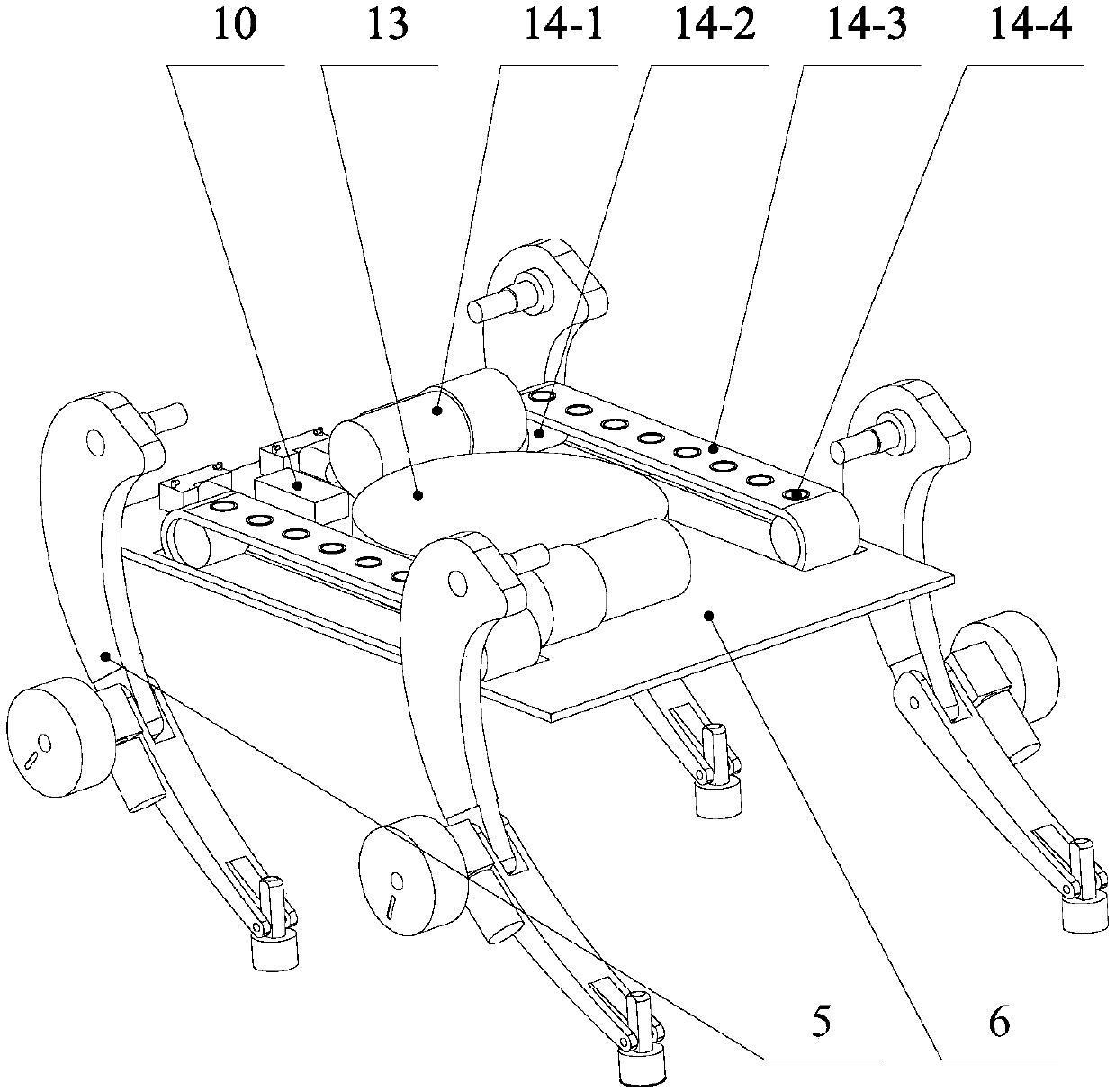
[0033] see figure 1 , figure 2 , image 3 and Figure 4 , the tunnel water seepage detection robot based on multi-sensor fusion provided by the preferred embodiment of the present invention, the tunnel water seepage detection robot can carry out 24-hour uninterrupted automatic detection without affecting the train operation, and can reduce the labor of the staff at the same time Intensive an...


PUM


Abstract

The invention belongs to the field of related technologies of tunnel seepage detection and discloses a tunnel seepage detection robot based on multi-sensor fusion. The tunnel seepage detection robot comprises a case with an opening, a case chassis connected to the case, a control circuit board hoisted to the case, at least three vacuum pumps, a big sucker, wheel legs and crawler walking modules, wherein the chassis is also provided with a groove and holes penetrating through the chassis; the big sucker is arranged in the groove and is provided with sucker legs; parts of the crawler walking modules pass through the holes, protrude from the chassis and are away from the surface of the case, and the crawler walking modules are also provided with small suckers; the at least three vacuum pumpsare respectively connected to the big sucker, the small suckers and the sucker legs; and the at least three vacuum pumps, the wheel legs and the crawler walking modules are electrically connected to the control circuit board respectively. The tunnel seepage detection robot disclosed by the invention improves the detection accuracy and is higher in applicability, lower in cost and higher in flexibility.

Description

technical field [0001] The invention belongs to the related technical field of tunnel water seepage detection, and more specifically relates to a tunnel water seepage detection robot based on multi-sensor fusion. Background technique [0002] With the advancement of science and technology and the development of the economy, people's demand for convenient travel is getting higher and higher. Cross-regional high-speed railways and subways in cities have emerged as the times require, and have become blooming everywhere. While a large number of rail transit facilities provide people with quality of life, there are also some problems. Due to China's vast territory and complex terrain, high-speed rail needs to pass through tunnels with different geological conditions; most of the subways shuttle through underground tunnels. During the shield tunneling process, lining blocks are mostly used to line the tunnel body. A large number of lining blocks form a patchwork with a total le...

Claims


Application Information

Patent Timeline
IPC IPC(8): B62D57/024B62D55/265G01M3/00G01M3/04
CPCG01M3/002G01M3/04B62D55/265B62D57/024Y02A90/30
Inventor 张立茂吴贤国张文静郑豪朱宏平陈虹宇姚春娇曾铁梅
Owner HUAZHONG UNIV OF SCI & TECH
Learn More