
A Method for Reducing Residual Stress of Laser Cladding Metal Coating

A metal coating and residual stress technology, applied in the direction of metal material coating process, coating, etc., can solve the problems of high processing cost, inability to prevent prevention, low production efficiency, etc., to reduce the accumulation of residual stress and reduce residual stress. The effect of leveling, avoiding cracks and cracks

Active Publication Date: 2021-02-05
NANJING UNIV OF AERONAUTICS & ASTRONAUTICS
View PDF1 Cites 0 Cited by
  • Summary
  • Abstract
  • Description
  • Claims
  • Application Information

AI Technical Summary

Problems solved by technology

[0004] First, optimize the process parameters from the aspects of laser power, spot diameter, scanning speed, overlapping rate, scanning strategy, etc., and change the stress distribution inside the part to reduce the residual stress, but the mechanical properties of the part cannot be taken into account;
[0005] Second, add a preheating module on the shaped substrate, heat the bottom of the substrate before the laser scans the substrate, reduce the temperature gradient between the formed part and the substrate, thereby reducing the residual stress caused by the excessive temperature gradient , but preheating the substrate will increase the complexity of the equipment and the difficulty of control;
[0006] Thirdly, post-treatments such as hot isostatic pressing and stress relief annealing are carried out on the formed parts to eliminate the residual stress inside the formed parts. Although the residual stress can be reduced to a certain extent, the parts will still be deformed and cracked after processing to the preventive effect;
[0007] Fourth, oxides such as MgO, CeO2, Y2O3 are added during the cladding process to reduce residual stress, but the addition of oxides makes the process complicated, the production efficiency low, and the processing cost high
[0008] In summary, in the prior art, there is a lack of a simple and low-cost method that can effectively reduce residual stress and avoid cracking of the molten metal layer

Method used


Image

  • A Method for Reducing Residual Stress of Laser Cladding Metal Coating
  • A Method for Reducing Residual Stress of Laser Cladding Metal Coating
  • A Method for Reducing Residual Stress of Laser Cladding Metal Coating

Examples


Embodiment Construction

[0030]In order to enable those skilled in the art to better understand the technical solutions of the present invention, the present invention will be further described in detail below in conjunction with specific embodiments.

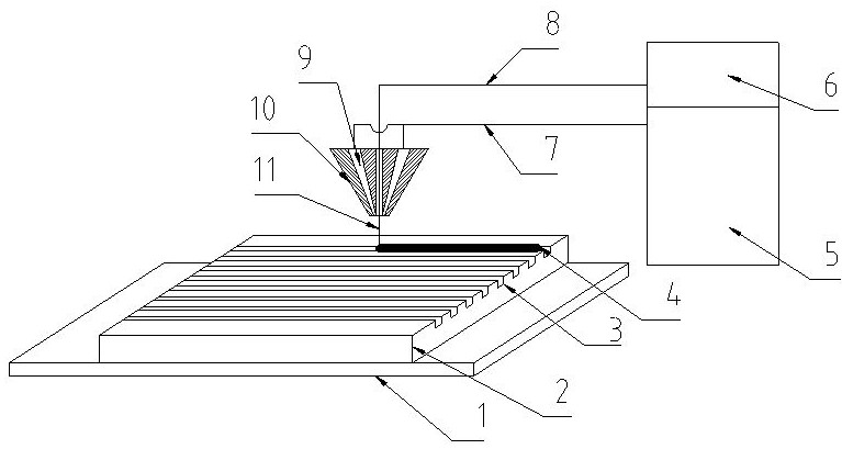
[0031]The device applicable to the embodiment of the present invention is such asfigure 1 As shown, it includes: bottom plate 1, substrate 2, groove 3, deposition layer 4, powder feeding system 5, laser system 6, powder delivery pipeline 7, laser delivery pipeline 8, powder delivery tank 9, powder delivery nozzle 10 .

[0032]A substrate 2 is fixedly installed on the bottom plate 1, and a groove 3 is burned out on the substrate 2. The powder feeding system 5 and the laser system 6 are connected to the powder feeding tank 9 through the powder feeding pipe 7 and the laser feeding pipe 8, and a powder feeding nozzle 10 is provided at the end of the powder feeding tank 9. The powder feeding nozzle 10 sprays metal powder to cover the surface of the substrate 2, and the...


PUM

PropertyMeasurementUnit
widthaaaaaaaaaa
diameteraaaaaaaaaa

Abstract

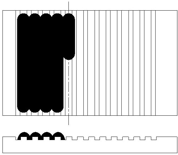
The invention discloses a method for reducing the residual stress of laser cladding metal coatings. Before cladding, the invention prefabricates regularly arranged groove microstructures on the substrate, and the laser focus falls on the center of two adjacent grooves. , the melting channel and the groove are parallel to each other. The invention is suitable for laser cladding technology, and is characterized in that the residual stress of formed parts is low, effectively avoids cracks, cracks, warping and deformation phenomena, does not require additional equipment, and is easy to operate.

Description

Technical field[0001]The invention relates to the field of laser processing, in particular to a method for reducing the residual stress of a laser cladding metal coating.Background technique[0002]Laser cladding is a method of using high-energy laser beams to cladding metal powder on a substrate to prepare a metal coating. This method has the advantages of high bonding strength with the substrate, low dilution rate, high hardness, wear resistance and corrosion resistance. . In recent years, surface modification and strengthening of key metal parts based on this technology has become a research hotspot and has shown broad application prospects. However, due to the uneven distribution of laser energy, the large temperature gradient during the cladding process, and the large solidification rate, the laser cladding cermet layer will cause cracks and other defects due to residual stress, and the cladding layer is easy to crack, which seriously restricts In order to promote its further pro...

Claims


Application Information

Patent Timeline
Patent Type & Authority Patents(China)
IPC IPC(8): C23C24/10
CPCC23C24/103
Inventor 赵剑峰王冠军谢德巧梁绘昕田宗军沈理达
Owner NANJING UNIV OF AERONAUTICS & ASTRONAUTICS
Learn More