Permanent magnet synchronous motor rotor component and manufacturing method thereof

A permanent magnet synchronous motor and rotor technology, applied in the direction of electric components, magnetic circuit rotating parts, electrical components, etc., can solve the problems of difficult installation and disassembly, affect the performance and energy consumption of the motor, and the temperature rise of the rotor, and achieve disassembly Easy maintenance, high pass rate, no effect of eddy current loss

Pending Publication Date: 2018-03-30
NINGBO PHASE MOTION CONTROL
View PDF0 Cites 3 Cited by
  • Summary
  • Abstract
  • Description
  • Claims
  • Application Information

AI Technical Summary

Problems solved by technology

The suction force of the magnetic steel is very large, and the inherent characteristics of the fragile magnetic steel easily lead to high material costs and low production efficiency of the rotor assembly in the design and manufacture; the installation and disassembly process of the rotor assembly structure in the prior art is difficult; The rotor assembly in the prior art has a large volume, and the interaction with the stator assembly during the working process causes the temperature of the rotor to rise due to the large amount of heat generated, which affects the performance and energy consumption of the motor; the permanent magnet of the rotor assembly in the prior art is prone to eddy currents loss

Method used


Image

  • Permanent magnet synchronous motor rotor component and manufacturing method thereof
  • Permanent magnet synchronous motor rotor component and manufacturing method thereof
  • Permanent magnet synchronous motor rotor component and manufacturing method thereof

Examples


Embodiment Construction

[0029] The following is based on Figure 1 to Figure 4 The specific embodiment of the present invention is further described:

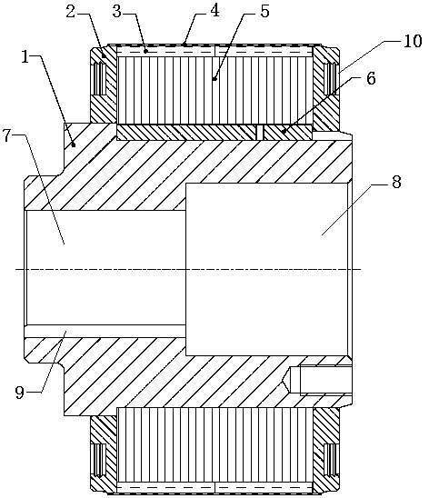
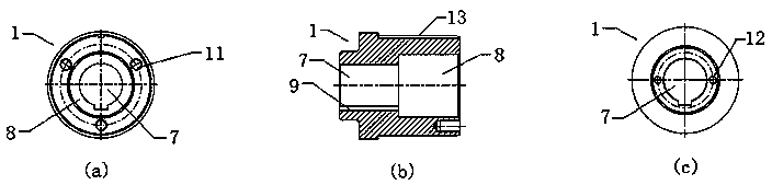
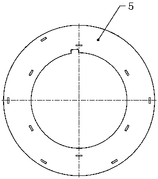
[0030] see figure 1 , a permanent magnet synchronous motor rotor assembly, including a rotating shaft 1, a balance ring 2, a magnetic steel 3, a carbon fiber sleeve 4, and a rotor core 5 (see image 3 ) and peace key 6, see figure 2 , figure 2 (a) is the right view of shaft 1, figure 2 (b) is the front cross-sectional view of the shaft 1, figure 2 (c) is the left view of the rotating shaft 1, the outer surface of the rotating shaft 1 is provided with a first U-shaped groove 13, the flat key 6 is arranged in the first U-shaped groove 13, and the rotor core 5 Sleeved on the outer surface of the rotating shaft 1 and the rotor iron core 5 is in interference connection with the rotating shaft 1, the balance ring 2 is sleeved on the end of the rotating shaft 1 and the balance ring 2 is respectively connected to the rotating shaft 1 and the rotor ir...


PUM


Abstract

The invention discloses a rotor assembly of a permanent magnet synchronous motor and a manufacturing method thereof, comprising a rotating shaft, a balance ring, magnetic steel, a carbon fiber sleeve, a rotor iron core and a flat key, and a first U-shaped groove is provided on the outer surface of the rotating shaft , the flat key is set in the first U-shaped groove, the rotor iron core is sleeved on the outer surface of the rotating shaft and the rotor iron core is in interference connection with the rotating shaft, and the balance ring is sleeved on the end of the rotating shaft and the balance ring is respectively connected with the rotating shaft and the rotor core in an interference fit, the magnetic steel is pasted on the outer surface of the rotor core, and the carbon fiber sleeve is sleeved on the outer surface of the magnetic steel and the balance ring, so The interior of the rotating shaft is provided with a first cylindrical shaft hole and a second cylindrical shaft hole connected to each other, and the first cylindrical shaft hole is larger than the second cylindrical shaft hole; the invention has simple structure, convenient installation, disassembly and maintenance, and is not easy Crushing, high pass rate, small size, less consumables, and less heat generated during operation.

Description

technical field [0001] The invention relates to the field of electromechanical technology, in particular to a permanent magnet synchronous motor rotor assembly and a manufacturing method thereof. Background technique [0002] The existing permanent magnet synchronous servo motor rotor assembly is composed of a rotating shaft with threaded holes, a rotor module or a combination of parts assembled with silicon steel sheets, magnetic steel and the like. The suction force of the magnetic steel is very large, and the inherent characteristics of the fragile magnetic steel easily lead to high material costs and low production efficiency in the design and manufacture of the rotor assembly; the installation and disassembly process of the rotor assembly structure in the prior art is difficult; The rotor assembly in the prior art has a large volume, and the interaction with the stator assembly during the working process causes the temperature of the rotor to rise due to the large amoun...

Claims


Application Information

Patent Timeline
Patent Type & Authority Applications(China)
IPC IPC(8): H02K1/27H02K7/04H02K1/22
CPCH02K1/2753H02K1/22H02K7/04
Inventor 徐杰安高峰侯跃岭徐世超竺湘灵冯钰卿
Owner NINGBO PHASE MOTION CONTROL
Why Eureka
Try Eureka