Fine double-sided planer

A double-sided planer and wood machine technology, which is applied in the direction of manufacturing flat surface processing machines, wood processing appliances, manufacturing tools, etc., can solve the problem of long production process flow, increased labor and human finished products, and lack of reliable compression constraints, etc. question

Pending Publication Date: 2018-04-03
JIANGSU JIANGJIA MACHINERY
View PDF9 Cites 7 Cited by
  • Summary
  • Abstract
  • Description
  • Claims
  • Application Information

AI Technical Summary

Problems solved by technology

[0004] With the continuous improvement of wood product processing quality and processing efficiency, higher requirements are put forward for the production efficiency and wood processing quality of double-sided wood planers. In this case, the existing double-sided wood planers have the following shortcomings: First of all, because the existing double-sided planer is only provided with a pair of planers, the upper planer completes the planing of the upper side of the wood, and the lower planer completes the planing of the lower side of the wood, so a double-sided planer can only complete For rough planing or fine planing of wood, two double-sided wood planers must be used to achieve rough planing and fine planing of wood, which not only has low production efficiency, but also increases the production process and increases labor and labor.
However, when this kind of presser foot is planed at high speed or with a large amount of planing, it often does not have the effect of reliably pressing and restricting the feeding of wood; The "head gnawing" phenomenon during the processing cannot well avoid the "tail gnawing" phenomenon of the wood on the discharge side of the planer. After planing, the wood is still in an unconstrained free state after entering the discharge side of the planer, which cannot satisfy Efficient, high-quality planing requirements

Method used


Image

  • Fine double-sided planer
  • Fine double-sided planer
  • Fine double-sided planer

Examples


Embodiment Construction

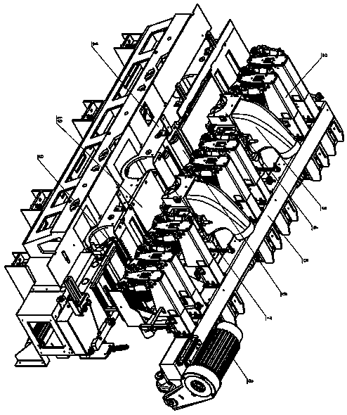
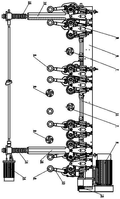
[0033] Such as figure 1 As shown in the fine double-sided planer, the double-sided planer includes a frame 1, and a workbench 10 is arranged on the frame 1, and the workbench 10 is used to support planed wood. Two lower planer knives 9 that can rotate at a high speed are supported on the frame 1 . Two upper planer knives 7 that can rotate at high speed are arranged above the table top of the work surface 10, and the cutter shafts of the two upper planer knives 7 are supported on the frame 1 through the upper planer shaft bearings, and the upper planer 7 and its cutter shafts are opposite to each other. The frame 1 can be adjusted by sliding up and down. The cutter shafts of the upper planer 7 and the lower planer 10 are connected to the planer motor through a belt transmission pair, and the axis lines of the upper planer 7 and the lower planer 10 are parallel to each other. There are also seven lower feeding rollers 6 that are rotatably supported on the frame 1, and the prop...


PUM


Abstract

The invention discloses a fine double-sided planer which comprises a machine frame, wherein two rotary lower plane cutters are supported by the machine frame, the positions of the two lower plane cutter corresponds to a work table, two rotary upper plane cutter are further arranged above the work table, and cutter shafts of the upper plane cutters and cutter shafts of the lower plane cutters are in parallel mutually; a plurality of lower feeding rollers are further supported by the machine frame in a rotary mode, the lower plane cutters and the lower feeding rollers are arranged in a mutuallystaggered mode, a plurality of upper feeding roller assemblies are arranged above the work table, the upper plane cutter and the upper feeding roller assemblies are arranged in a staggered mode, and feeding roller spindles of the upper feeding roller assemblies are parallel to the axes of the lower feeding rollers; the feeding roller spindles and the lower feeding rollers are connected with a feeding roller speed reducer respectively through upper feeding roller driving cardan joints and lower feeding roller driving cardan joints. The planer can provide strong, powerful and stable pushing feeding force and a reliable press restraining effect for wood; furthermore, the planer can achieve one-step type rough planing and fine planing on the wood.

Description

technical field [0001] The invention relates to the technical field of wood processing, in particular to a double-sided wood planer which has upper and lower push feeding rollers and can realize parallel advance of multiple wood materials. Background technique [0002] A wood planer is a woodworking machine that planes the surface of wood made of rough material of specifications. It can plan wood of different specifications into shaped board-shaped or rod-shaped net materials of different thicknesses. Planer machine tools mainly include double-sided planers and four-sided planers. The main working parts of the double-sided planer are the horizontally installed upper and lower planer shafts, the planer mounted on the planer shaft, and the up and down push feed rollers. The pair of feeding rollers is composed of a pair of feeding rollers; the planer shaft and its planer complete the planing of the surface of the wood wool, and the feeding roller completes the feeding and pushi...

Claims


Application Information

Patent Timeline
Patent Type & Authority Applications(China)
IPC IPC(8): B27C1/08
CPCB27C1/08
Inventor 朱志林邹小祥王均东
Owner JIANGSU JIANGJIA MACHINERY
Why Eureka
Try Eureka