Support used for implanting blood vessel

A technology of blood vessels and supporting force, which is applied in the field of stents for carotid artery treatment, and can solve problems such as plaque shedding, stent displacement, and cerebral ischemic events

Pending Publication Date: 2018-04-06
SUZHOU INNOMED MEDICAL DEVICE
View PDF0 Cites 9 Cited by
  • Summary
  • Abstract
  • Description
  • Claims
  • Application Information

AI Technical Summary

Problems solved by technology

[0003] Although compared with surgery, vascular stent has a better therapeutic effect, but it still has certain limitations.
For example, carotid artery stenosis is mainly caused by plaques growing on the intima of blood vessels, and such plaques are mostly atherosclerotic, unstable, and prone to ulceration. The lipid components in the plaques are exposed in the blood vessel lumen, resulting in Platelets aggregate to form a thrombus, and the thrombus falls off. When the conventional bare stent is implanted in the blood vessel, the radial cutting effect will occur when the stent expands or contracts in the blood vessel, which will cause the plaque on the vessel wall to enter the stent
prone to cerebral ischemic events
Although the fully covered stent is used to solve the problem of plaque shedding, due to the smooth surface of the fully covered stent, the stent implanted in the blood vessel is prone to shift in the blood vessel due to the influence of blood flow

Method used


Image

  • Support used for implanting blood vessel
  • Support used for implanting blood vessel
  • Support used for implanting blood vessel

Examples


Embodiment approach 1

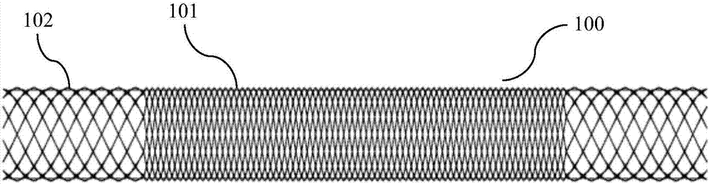
[0035] figure 1 It is a structural schematic diagram of an example of a stent for implanting a blood vessel according to Embodiment 1 of the present invention. like figure 1 As shown, the stent 100 provided in this embodiment is a cylindrical stent with the same diameter of each section, which includes a section 101 for preventing the plaque on the inner wall of the blood vessel from entering the stent and a supporting section 102 . Among them, there is one section 101 for preventing the plaque on the inner wall of the blood vessel from entering the stent, which is located in the middle of the stent 100 ; The overall length of the bracket 100 is 20mm. The length of each support section 102 accounts for 20% of the length of the stent 100 . In this embodiment, both the section 101 and the support section 102 for preventing the plaque on the inner wall of the blood vessel from entering the stent are of a single-layer structure, and are integrally woven from braided silk. The ...

Embodiment approach 2

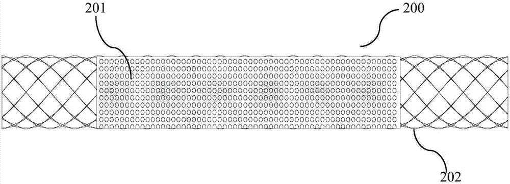
[0040] image 3 It is a structural schematic diagram of an example of a stent for implanting into a blood vessel according to Embodiment 2 of the present invention. like image 3As shown, the stent 200 provided in this embodiment is a cylindrical stent with the same diameter of each section, which includes a section 201 for preventing the plaque on the inner wall of the blood vessel from entering the stent and a supporting section 202 . Among them, there is one section 201 for preventing the plaque on the inner wall of the blood vessel from entering the stent, which is located in the middle of the stent 200 ; The overall length of the bracket 200 is 20mm. The length of each support section 202 accounts for 20% of the length of the stent 200 . In this embodiment, the section 201 for preventing the plaque on the inner wall of the blood vessel from entering the stent is a multi-layer structure, which has a base layer woven from braided silk and a coating layer covering the out...

Embodiment approach 3

[0046] Figure 7 It is a structural schematic diagram of an example of a stent for implanting into a blood vessel according to Embodiment 3 of the present invention. like Figure 7 As shown, the stent 300 provided in this embodiment is a cylindrical stent with the same diameter of each section, which includes a section 301 for preventing the plaque on the inner wall of the blood vessel from entering the stent and a supporting section 302 . Among them, there is one section 301 for preventing the plaque on the inner wall of the blood vessel from entering the stent, which is located in the middle of the stent 300 ; The overall length of the bracket 300 is 20mm. The length of each support section 302 accounts for 20% of the length of the stent 300 . In this embodiment, the section 301 for preventing the plaque on the inner wall of the blood vessel from entering the stent is a multi-layer structure, which has a base layer woven from braided silk and a braided mesh layer covering...


PUM


Abstract

The invention provides a support used for implanting the blood vessel. The support comprises a section for preventing blood vessel inner wall plaques from entering the support and a supporting section, wherein the section for preventing the blood vessel inner wall plaques frim entering the support is suitable for stopping the plaques on the inner wall of blood vessel from entering the support; thesupporting section provides supporting force enough to prevent the support against displacement in the blood vessel; the pore density of the section for preventing the blood vessel inner wall plaquesfor entering the support is larger than that of the supporting section. The support can effectively stop the plaques on the inner wall of the blood vessel from entering the support, and the support can also be prevented against displacement in the blood vessel.

Description

technical field [0001] The invention relates to a stent for implanting blood vessels, in particular to a stent suitable for carotid artery treatment. Background technique [0002] In recent years, minimally invasive endovascular treatment techniques in vascular surgery have made great progress, and vascular stents have been widely used in the treatment of systemic vascular diseases. According to the distribution of lesions, different vascular stents can be mainly used for peripheral vascular lesions, small artery lesions, aortic lesions, and venous lesions; Restenosis etc. [0003] Although compared with surgery, vascular stent has a better therapeutic effect, but it still has certain limitations. For example, carotid artery stenosis is mainly caused by plaques growing on the intima of blood vessels, and such plaques are mostly atherosclerotic, unstable, and prone to ulceration. The lipid components in the plaques are exposed in the blood vessel lumen, resulting in Platel...

Claims


Application Information

Patent Timeline
Patent Type & Authority Applications(China)
IPC IPC(8): A61F2/915A61F2/89A61M31/00A61F2/848
CPCA61F2/915A61F2/89A61F2002/8483A61M31/00
Inventor 曲乐丰柏骏赫明龚霄雁魏继昌
Owner SUZHOU INNOMED MEDICAL DEVICE
Why Eureka
Try Eureka