Extrusion die for biomass fuel

A biomass fuel, extrusion die technology, applied in the direction of biofuel, waste fuel, fuel, etc., can solve the problems of increasing the production cost of biomass fuel, affecting the combustion effect of biomass fuel particles, and high density of biomass fuel. Improve the scope of use, save manpower and material resources, and facilitate maintenance.

Active Publication Date: 2020-08-28
利辛县逸安新能源有限公司
View PDF6 Cites 0 Cited by
  • Summary
  • Abstract
  • Description
  • Claims
  • Application Information

AI Technical Summary

Problems solved by technology

In the existing biomass fuel production enterprises, different types of biomass fuels are basically extruded and granulated through extrusion dies of different specifications, so different biomass fuels basically require extrusion dies of different specifications. Increase the production cost of biomass fuel, and the density of biomass fuel produced by ordinary extrusion machinery is relatively high, thus affecting the combustion effect of biomass fuel particles

Method used


Image

  • Extrusion die for biomass fuel
  • Extrusion die for biomass fuel
  • Extrusion die for biomass fuel

Examples


Embodiment 1

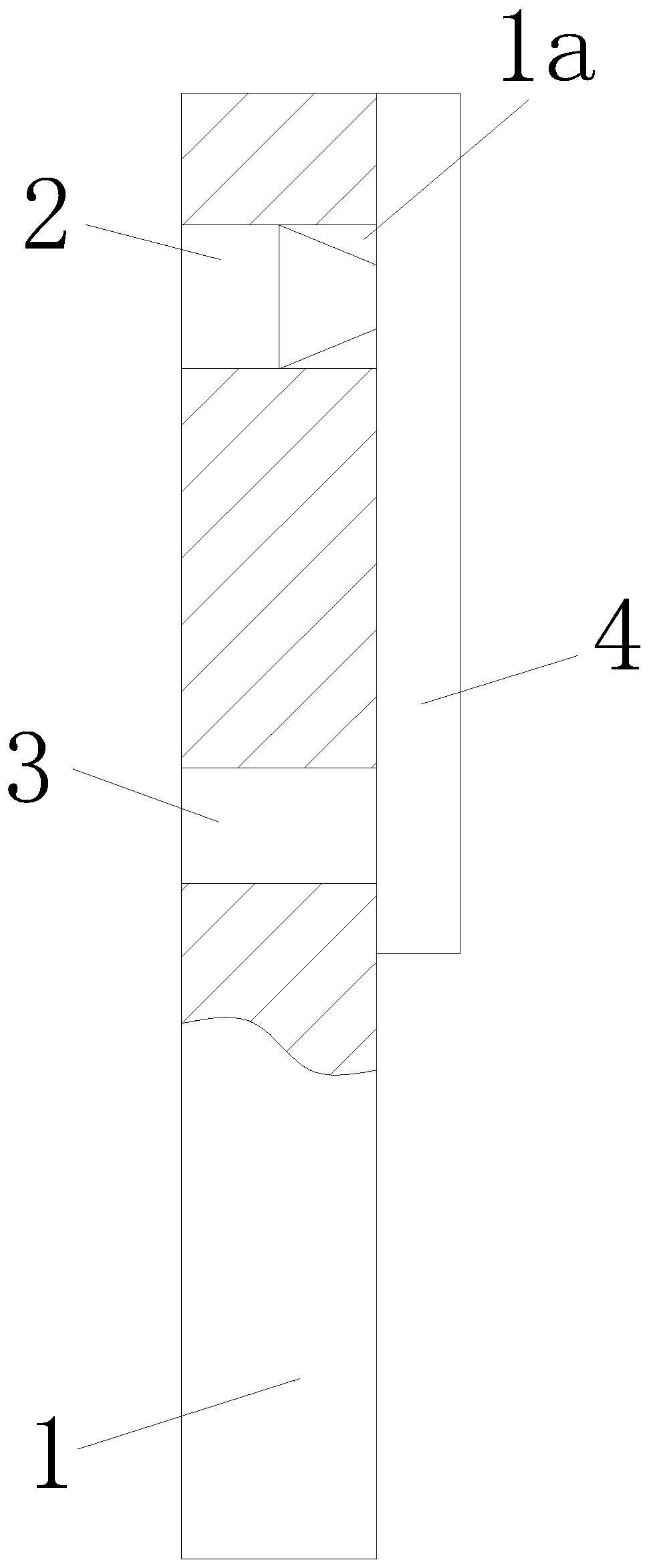
[0024] Such as Figure 1 to Figure 2 As shown, an extrusion die for biomass fuel includes a positioning head 1, a plurality of through holes 1a are provided on the positioning head 1, and a pelletizing unit 2 and a positioning head 1 are installed in the through holes 1a in a detachable manner. A rotating shaft 3 is also installed on the rotating shaft 3, a segmented knife 4 is installed on the rotating shaft 3, and the rotating shaft 3 is connected with the positioning shaft. When in use, the shaft 3 is connected with an external power source, the external power source drives the shaft 3 to rotate, and the shaft 3 drives the segmented knife 4 to rotate, cutting off the long strip of biomass fuel to form particles, instead of the traditional passing The method of self-weight forming, and the pelletizing unit 2 of different specifications can be replaced according to different types of biomass fuel, which improves the use range of the device, is convenient for maintenance, and s...

Embodiment 2

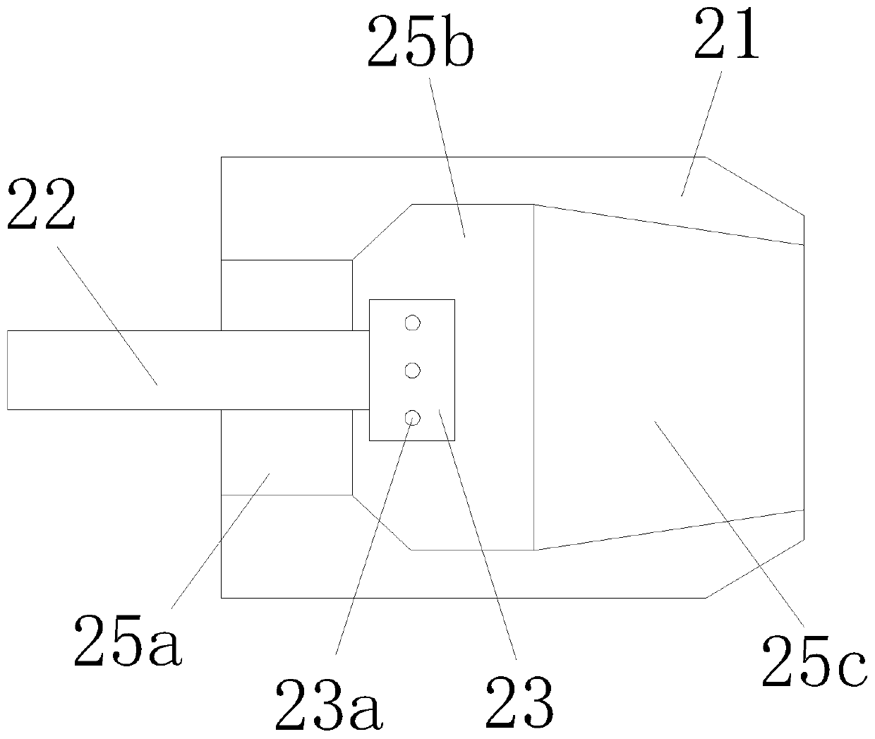
[0033] Such as image 3 As shown, the difference from the first embodiment is that the gas filling head 23 is arranged in the lead cavity 25a, which can speed up the flow rate of the biomass fuel during the extrusion molding process to form uneven Air bubbles increase the combustion efficiency of biomass fuel.

Embodiment 3

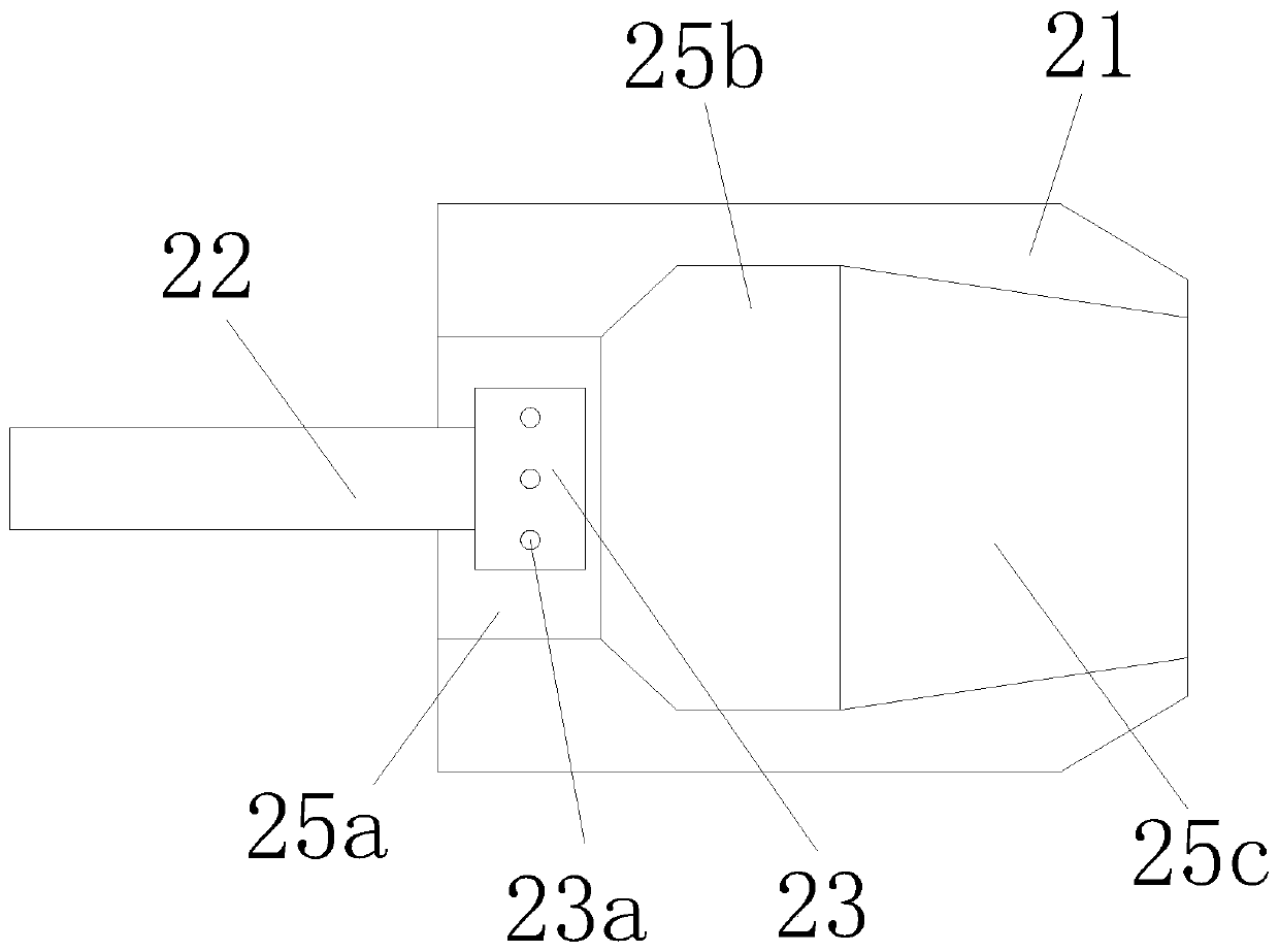
[0035] Such as Figure 4 As shown, the difference from the first embodiment is that the gas filling head 23 is a hemispherical gas filling head, which can make the biomass fuel form smaller holes during the extrusion process, thereby reducing the biomass fuel The amount of deformation ensures the structural strength of the biomass fuel.

[0036] When in use, the biomass fuel is squeezed into the molding channel on the mold cavity 21, the biomass fuel passes through the duct 22 to form a hollow structure, and in the process, the external gas source works to send the gas into the duct 22, and the gas passes through The gas filling head 23 on the duct 22 physically fills the biomass fuel in the mold cavity 21, so that holes are formed in the hollow structure of the biomass fuel, and the natural foaming of the biomass fuel is realized. At the same time, the external power source works. The rotating shaft 3 is driven to rotate, and the rotating shaft 3 drives the segmented knife 4 to ...


PUM


Abstract

The invention discloses an extrusion die for biomass fuel. The extrusion die comprises a positioning head, wherein a plurality of through holes are formed in the positioning head; granulation units are arranged in the through holes in a detachable manner; a rotating shaft is arranged on the positioning head; a segmenting knife is arranged on the rotating shaft; and the rotating shaft is connectedwith a positioning shaft. According to the extrusion die disclosed by the invention, the granulation units are arranged in the detachable manner, so that granulation of different types of biomass fuelis realized, the application range of the device is widened, the maintenance is convenient, and the manpower and material resources are saved. Moreover, the produced biomass fuel has a hollow structure, and is large in contact area with oxygen and high in combustion efficiency.

Description

Technical field [0001] The invention relates to the technical field of production equipment for biomass fuels, in particular to an extrusion die for biomass fuels. Background technique [0002] With the development of the times, more and more biomass fuels are used, and the biomass fuel manufacturing industry has achieved unprecedented development. Biomass fuel refers to a new type of clean fuel that uses biomass materials as raw materials and undergoes pulverization, mixing, extrusion, and drying processes to make various shapes and can be directly burned. In the existing biomass fuel production enterprises, different types of biomass fuels are basically extruded and pelletized through different specifications of extrusion dies. Therefore, different biomass fuels basically require different specifications of extrusion dies. Increasing the production cost of biomass fuel, and the density of biomass fuel produced by ordinary extrusion machinery is relatively high, thus affecting ...

Claims


Application Information

Patent Timeline
Patent Type & Authority Patents(China)
IPC IPC(8): B01J2/22C10L5/44
CPCB01J2/22C10L5/44Y02E50/10Y02E50/30
Inventor 刘志和
Owner 利辛县逸安新能源有限公司
Why Eureka
Try Eureka