
Steel rail plasma alloy cladding method

A technology of plasma cladding and plasma, which is applied in the field of rail cladding, can solve problems such as limited use of cladding alloys, overweight equipment, and slow cladding moving speed, so as to improve cladding applicability and cladding efficiency, and improve Corrosion and wear resistance properties, effects of volume and weight reduction

Active Publication Date: 2018-04-06
CHENGDU ZHONGGUI TECH CO LTD
View PDF6 Cites 0 Cited by
  • Summary
  • Abstract
  • Description
  • Claims
  • Application Information

AI Technical Summary

Problems solved by technology

[0012] 2. Generator power is used for cladding site construction. If the power of the generator exceeds 40kw, the equipment is too heavy to be transported manually
The cladding moving speed is too slow, usually the cladding speed is 30-40m / h, and the section with poor branching is generally 60-100m / place, while the working time of the skylight is only 1h / day, and the construction of one bad branching section requires 2 -3 days, low construction efficiency and high cost
[0013] 3. In northern my country and high-altitude areas, the temperature in winter is low, and the existing methods of cladding alloys are limited.

Method used

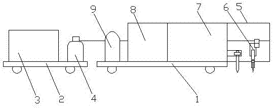
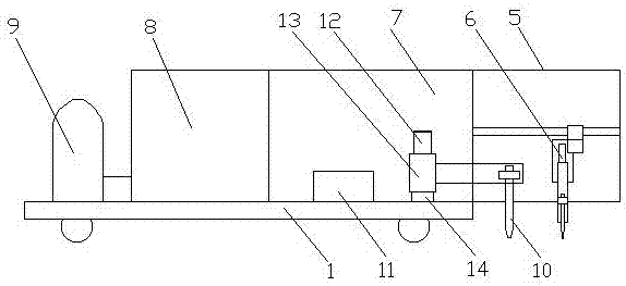

Image

  • Steel rail plasma alloy cladding method
  • Steel rail plasma alloy cladding method
  • Steel rail plasma alloy cladding method

Examples


Embodiment 1

[0062] A steel rail plasma cladding alloy method, comprising the following steps:

[0063] a. Place the rail cladding machine on the rail, the plasma welding torch 10 on the rail cladding machine moves at a constant speed with the first mobile trolley 1, and the plasma welding torch 10 cladding alloy above the rail head tread surface to be clad;

[0064] b. The alloy strip formed after alloy cladding is located on the inner side of the center of the rail head tread, the width of the alloy strip is 4mm, and the thickness of the heat-affected zone of the rail is controlled at 0.3mm.

Embodiment 2

[0066] A steel rail plasma cladding alloy method, comprising the following steps:

[0067] a. Place the rail cladding machine on the rail, the plasma welding torch 10 on the rail cladding machine moves at a constant speed with the first mobile trolley 1, and the plasma welding torch 10 cladding alloy above the rail head tread surface to be clad;

[0068] b. The alloy strip formed after alloy cladding is located on the inner side of the center of the rail head tread, the width of the alloy strip is 10mm, and the thickness of the heat-affected zone of the rail is controlled at 0.8mm.

[0069] In the step a, the chemical composition weight percentage of the alloy is: 1% B, 2% Si and the rest Ni.

Embodiment 3

[0071] A steel rail plasma cladding alloy method, comprising the following steps:

[0072] a. Place the rail cladding machine on the rail, the plasma welding torch 10 on the rail cladding machine moves at a constant speed with the first mobile trolley 1, and the plasma welding torch 10 cladding alloy above the rail head tread surface to be clad;

[0073]b. The alloy strip formed after alloy cladding is located on the inner side of the center of the rail head tread. The width of the alloy strip is 15mm, and the thickness of the heat-affected zone of the rail is controlled at 1.2mm.

[0074] In the step a, the chemical composition weight percent of the alloy is: 0.1% of C, 0.1% of Cr, 1.2% of B, 2% of Fe, 0.1% of Mn, 3% of Si, 0.1% of Mo and the rest Amount of Ni.


PUM


Abstract

The invention discloses a steel rail plasma alloy cladding method, and belongs to the technical field of rail cladding. The steel rail plasma alloy cladding method is characterized in that the steel rail plasma alloy cladding method comprises the following steps that a, a steel rail cladding machine is placed on the steel rail, a plasma welding gun on the steel rail cladding machine moves along with a first moving trolley at a uniform speed, the plasma welding gun conducts alloy cladding on the upper part of a to-be-cladded part of a tread face of a steel rail head; and b, an alloy belt formedafter alloy cladding is located at the center, inclined to the inner side, of the tread face of the steel rail head, the width of the alloy belt is 4-40 mm, and the thickness of a heat influence zoneof the steel rail is controlled to be 0.3-3 mm. According to the steel rail plasma alloy cladding method, the cooling speed of a cladding heat influence zone is not required to be controlled, the size and the weight of the steel rail cladding machine can be reduced, and the cladding applicability and the cladding efficiency are improved.

Description

technical field [0001] The invention relates to the technical field of rail cladding, in particular to a method for plasma cladding alloys of steel rails. Background technique [0002] The track circuit is an electrical circuit composed of two rails of the railway line as conductors, and the signal power supply and receiving equipment are connected with lead wires. In sections where trains rarely pass through for a long time, such as shunting lines, cargo lines, and special lines, the rail surface is severely oxidized and rusted. On, indicating that the track circuit has lost the function of checking the occupancy status of the track section. This phenomenon is called poor track circuit shunting. Cladding a layer of anti-rust and wear-resistant alloy belt on the rail head tread in the bad section of the track circuit, so that the wheel and the non-rust wear-resistant alloy belt can be effectively contacted, which can effectively eliminate the bad phenomenon of the track ci...

Claims


Application Information

Patent Timeline
IPC IPC(8): B23K10/02B23K37/00
CPCB23K10/027B23K37/00B23K37/003
Inventor 周厚全
Owner CHENGDU ZHONGGUI TECH CO LTD
Learn More