High density anti-compression optical fiber bundle optical cable for data center

A high-density, optical fiber bundle technology, used in the field of optical cables, can solve the problems of poor cold resistance, poor mechanical properties, and inapplicability of the outer sheath, and achieve the effect of light optical cable weight, wear resistance, and small outer diameter.

Pending Publication Date: 2018-04-06
JIANGSU HENGTONG PHOTOELECTRIC
View PDF0 Cites 3 Cited by
  • Summary
  • Abstract
  • Description
  • Claims
  • Application Information

AI Technical Summary

Problems solved by technology

Traditional MPO cables have poor tensile and compressive mechanical properties, and some outer sheaths have poor cold resistance, so they cannot be applied to high-density switch backplanes or fiber optic cabling solutions in data center computer rooms.

Method used


Image

  • High density anti-compression optical fiber bundle optical cable for data center
  • High density anti-compression optical fiber bundle optical cable for data center
  • High density anti-compression optical fiber bundle optical cable for data center

Examples


Embodiment 1

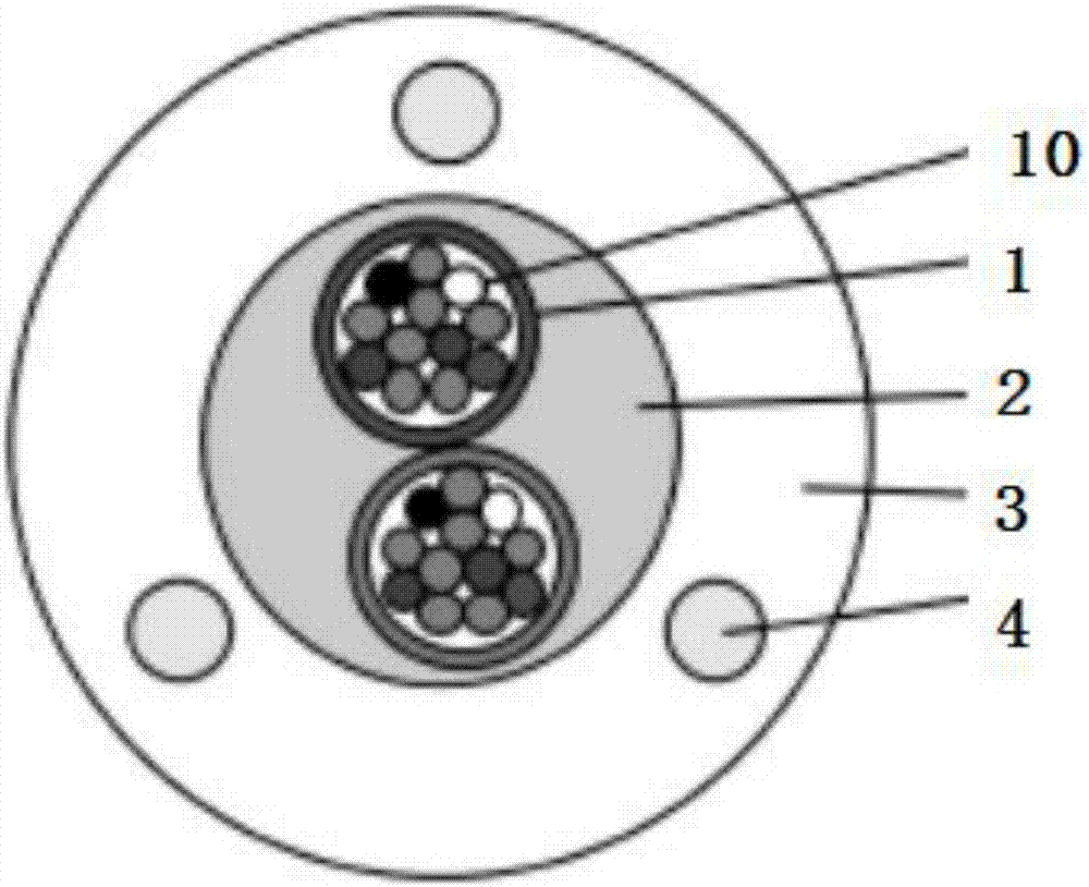
[0025] Embodiment 1 discloses a high-density compression-resistant optical fiber bundle cable for data centers, which includes: a micro-bundle tube optical fiber 1, a number of optical fibers 10 are arranged in the micro-bundle tube fiber 1, and are coated on the micro-bundle tube The aramid fiber layer 2 on the outside of the optical fiber 1, and the sheath layer 3 coated on the outside of the aramid fiber layer 2, and the three non-metallic strength members 4 are embedded in the sheath layer 3, and the three non-metal strength members 4 are composed of triangle.

[0026] The angle between the three non-metallic reinforcements is 120°, and the stability of the equilateral triangle ensures the beauty and good mechanical properties of the optical cable section; the outer diameter of the optical cable is 5.0±0.2mm; the thickness of the sheath layer 1.1±0.1mm, the thinnest point is not less than 0.9mm, each of the non-metallic reinforcements is embedded in the middle of the sheat...

Embodiment 2

[0032] The structure in Example 2 is as in Example 1. In parts by weight, the formula of the sheath layer includes: 30 parts of polyurethane, 30 parts of polyvinyl chloride, 8 parts of polyoxyalkylene modified polymethylsiloxane, 25 parts of nitrile rubber, 1.5 parts of dibutoxyethyl adipate, 1 part of trioctyl phosphate, 1.5 parts of modified carbon fiber, 2 parts of ammonium polyphosphate, 0.5 parts of zinc oxide, and 0.5 parts of accelerator DM. Wherein, the length of the modified carbon fiber is 1-10 μm, and the particle size of the zinc oxide is 600 mesh.

[0033] The modified carbon fiber is prepared through the following steps: take 2% of the aluminate coupling agent equivalent to the weight of the carbon fiber, add it to the DMF solution, heat to 80°C until the aluminate coupling agent is completely dissolved, and the aluminate coupling agent The mass ratio of the coupling agent to the DMF solution is 1:20; then the carbon fiber is added to the DMF solution, and centri...

Embodiment 3

[0039] In this embodiment, in parts by weight, the formula of the sheath layer includes: 20 parts of polyurethane, 35 parts of polyvinyl chloride, 12 parts of polyoxyalkylene modified polymethylsiloxane, 25 parts of nitrile rubber, 2 parts of dibutoxyethyl adipate, 1 part of trioctyl phosphate, 0.5 parts of modified carbon nanotubes, 3.5 parts of magnesium hydroxide, 0.4 parts of calcium carbonate, and 0.6 parts of accelerator DM. Wherein, the length of the modified carbon nanotube is 1-10 μm, and the particle size of the calcium carbonate is 800 mesh.

[0040] The modified carbon nanotubes are prepared through the following steps: take an aluminate coupling agent equivalent to 2% of the weight of the carbon nanotubes, add it to the DMF solution, and heat it to 80 ° C until the aluminate coupling agent is completely dissolved. The mass ratio of aluminate coupling agent to DMF solution is 1:20; then carbon nanotubes are added to the DMF solution, and centrifuged at 80°C for 2 h...


PUM


Abstract

The invention discloses a high density anti-compression optical fiber bundle optical cable for a data center. The optical fiber herein includes a micro-beam optical fiber, an aramid fiber layer whichcoats outside the micro-beam optical fiber, and a sheath layer which coats outside the aramid fiber layer. The sheath layer is embedded with three non-metal reinforcing members therein. The three non-metal reinforcing members constitute a triangle. The material of the sheath layer is composed of the following components by weight: polyurethane of 20-40 parts, polyvinyl choride of 25-45 parts, polyoxyalkylene modified polymethyl siloxane of 5-15 parts, chemigum of 20-30 parts, dibutoxyethyl adipate of 0.5-2 parts, trioctyl phosphate of 0.4-1 parts, modified filling material of 0.5-2 parts, a fire retardant of 2-4 parts, an activator of 0.2-0.6 parts, and a promoter of 0.5-1 parts. According to the invention, the optical fiber uses a center tubular structure, can ensure the moulding processof the optical fiber free from impact, and can also meet higher mechanical and environmental performances of the optical fiber.

Description

technical field [0001] The invention relates to the field of optical cables, in particular to a high-density compression-resistant optical fiber bundle optical cable for data centers. Background technique [0002] High-density compression fiber optic cable for data centers is a new concept product specially proposed for data center wiring. Traditional MPO cables are roughly divided into two categories: combined micro-bundle tube cables and bare fiber bundle cables. Traditional MPO cables have poor tensile and compressive mechanical properties, and some outer sheaths have poor cold resistance, so they cannot be applied to high-density switch backplanes or fiber optic cabling solutions in data center computer rooms. Contents of the invention [0003] The technical problem to be solved by the present invention is how to make the optical cable meet certain performances of lateral pressure resistance and bending resistance, and adopt a low-smoke and halogen-free sheath, and at...

Claims


Application Information

Patent Timeline
Patent Type & Authority Applications(China)
IPC IPC(8): G02B6/44
CPCG02B6/441G02B6/4432
Inventor 王胡江林卫峰高峰王宇亮蒋北刘沛东沈晨曦胡静红
Owner JIANGSU HENGTONG PHOTOELECTRIC
Why Eureka
Try Eureka