Machining equipment integrating punching and cutting

A kind of processing equipment and punching technology, which is applied in the field of machining auxiliary equipment, can solve the problems such as difficult to process the holes on the thin-walled cone-shaped workpiece cylinder, and achieve the effect of simple and practical structure, avoiding punching deviation, and convenient replacement

Pending Publication Date: 2018-04-10
安徽省华夏机床制造有限公司
View PDF1 Cites 3 Cited by
  • Summary
  • Abstract
  • Description
  • Claims
  • Application Information

AI Technical Summary

Problems solved by technology

[0008] The invention provides a special punching device for cone-shaped workpieces, which aims to solve the problem that the existing drilling equipment is difficult to process holes on the cylinder of thin-walled cone-shaped workpieces

Method used


Image

  • Machining equipment integrating punching and cutting
  • Machining equipment integrating punching and cutting
  • Machining equipment integrating punching and cutting

Examples


Embodiment 1

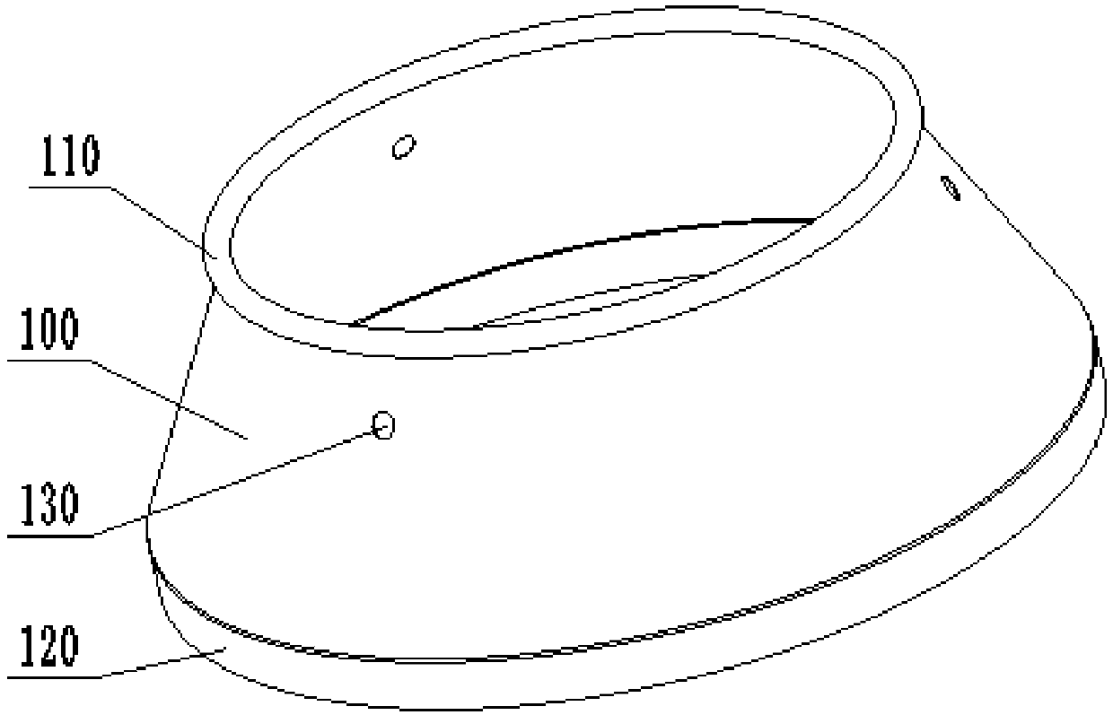
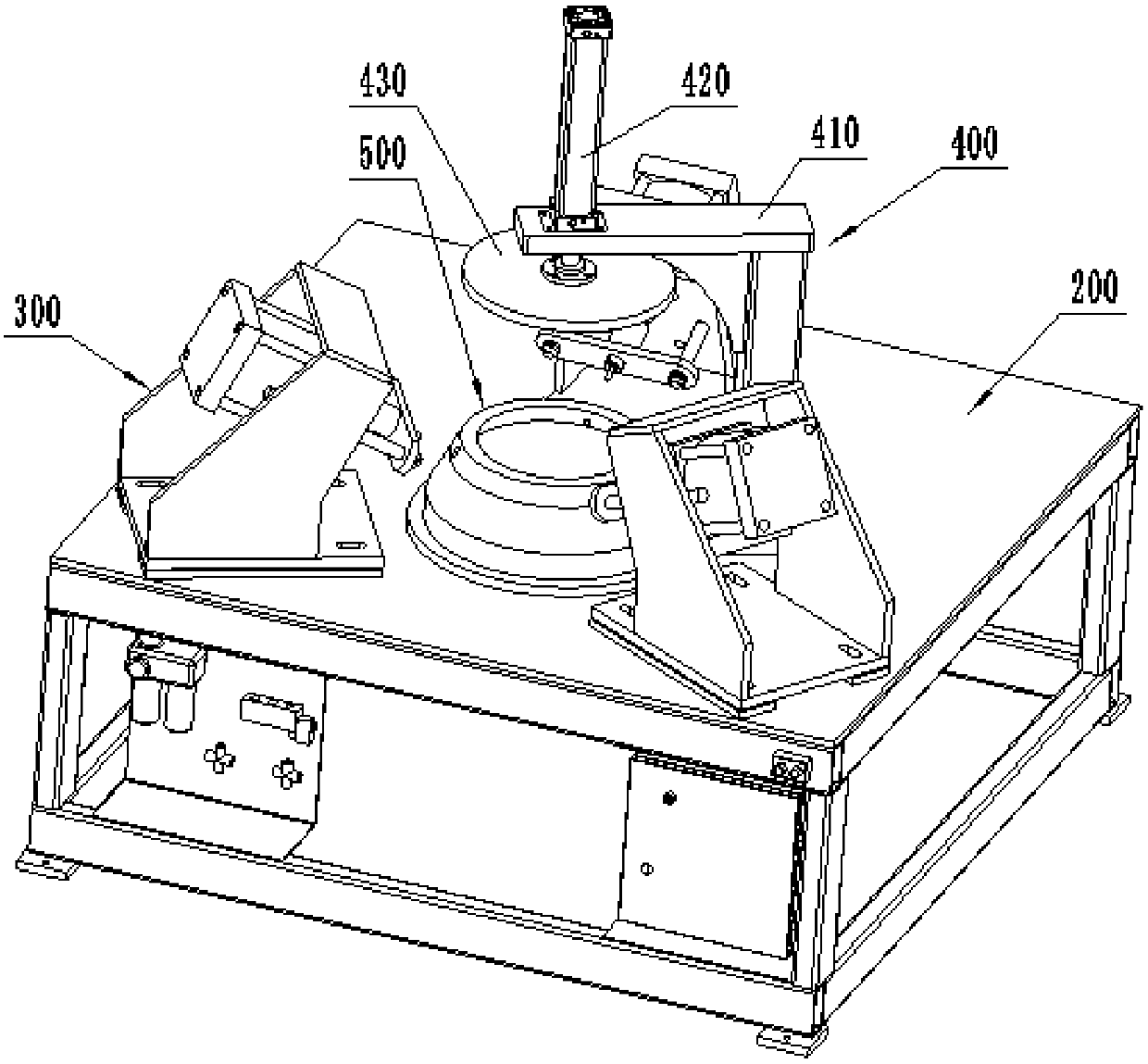
[0056] Such as figure 2 As shown, this embodiment is a special punching device for cone-shaped workpieces, which is mainly used for figure 1 The cone-shaped workpiece shown is punched. The cone-shaped workpiece is a thin-walled part with a wall thickness of 2 to 4mm. The edge extends vertically downward for a certain distance to form a circular edge 120 ; meanwhile, there are three holes 130 uniformly distributed along the circumferential direction on the barrel 100 . In actual production, it is necessary to process the hole 130 on the barrel 100. Due to the thin wall thickness of the workpiece, drilling with a general drilling machine will cause the edge of the hole to be depressed, the hole is not round, and the workpiece may be deformed as a whole. The problem to be solved by the embodiment.

[0057] The special punching device for conical cylindrical workpieces in this embodiment includes a frame 200 , and a punching assembly 300 , a supporting mold 500 and a pressing ...

Embodiment 2

[0063] The method for using a special punching device for a cone-shaped workpiece in this embodiment uses the special punching device for a cone-shaped workpiece in Embodiment 1 to punch the hole 130 on the cylinder body 100 of the cone-shaped workpiece, and its specific steps as follows:

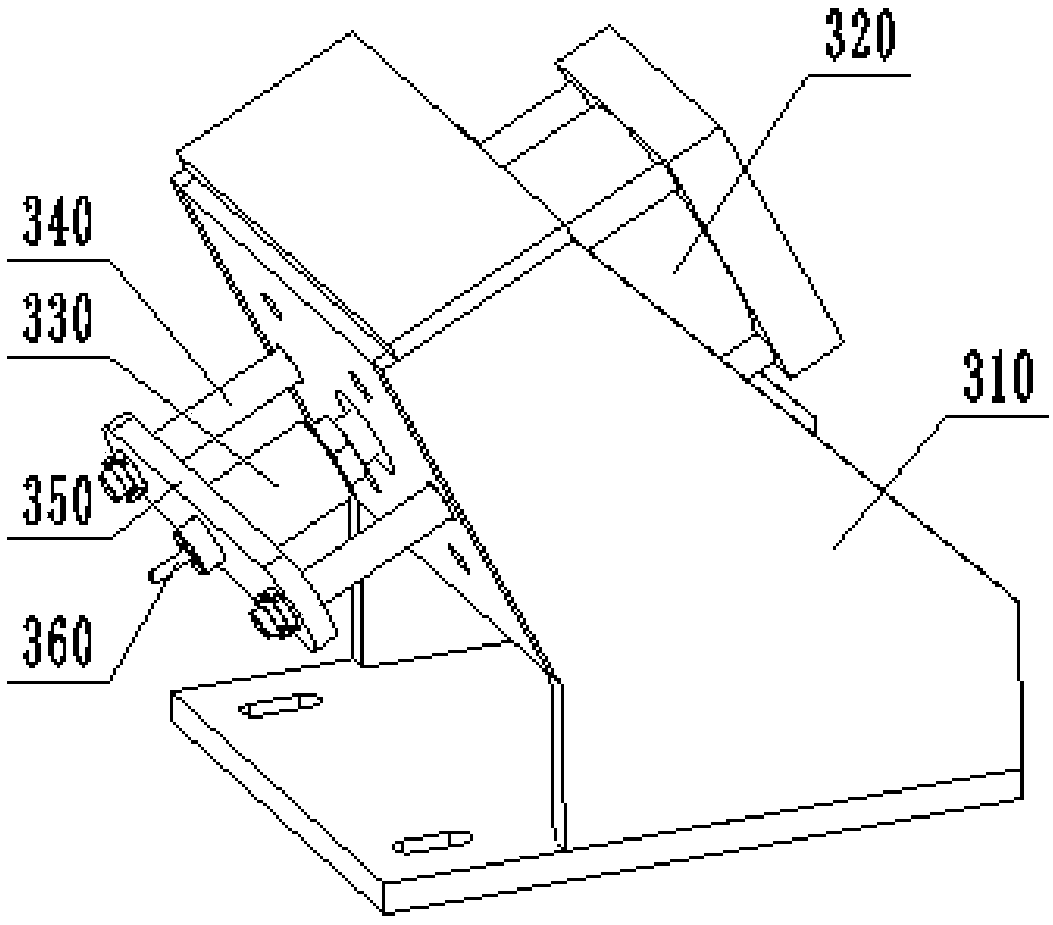
[0064] First, according to the diameter of the hole 130, select the corresponding punch 360 and die sleeve, and install the punch 360 on the shaft sleeve 330, and the die sleeve is inserted into the die hole 530 of the supporting mold 500;

[0065] Secondly, the punching assembly 300 moves, the punching cylinder 320 drives the extension of the punch 360, drives the punch 360 close to the supporting die 500, adjusts the direction of the supporting die 500, and ensures that the punch 360 can be accurately inserted into the die sleeve for pre-treatment. Calibration punching accuracy;

[0066] Then, the punching assembly 300 moves, and the punching cylinder 320 drives the punch 360 to shrink, ...

Embodiment 3

[0072] In actual use, sometimes the hole 130 on the cone-shaped workpiece cylinder 100 is not punched out at one time. When the diameter of the hole 130 is large, generally the smaller hole is punched out first, and then the hole is further expanded to punch out a large hole; At this time, the three punching assemblies 300 do not work at the same time, but work in sequence. The first punching assembly 300 punches out the pin hole, the second punching assembly 300 expands the hole, and the third punching assembly 300 Used for proofreading. At this time, the workpiece needs to be rotated to the next punching assembly 300 at a certain angle after being processed by the last punching assembly 300 .

[0073] For this reason, a special punching device for cone-shaped workpieces in this embodiment is further improved on the basis of Embodiment 1, and the supporting mold 500 is fixed on the rotating disk 750, and the rotating disk 750 is installed on the rotating disk 750 through bear...


PUM


Abstract

The invention discloses punching and cutting integrated processing equipment, which belongs to the field of machining auxiliary equipment. It includes a punching assembly, a supporting mold, an edge cutting assembly for driving the cutter, a turntable mechanism for driving the rotating disk and a locking mechanism for driving the rotating disk; the supporting mold is arranged on the rotating disk Its shape matches the shape of the inner hole of the cone-shaped workpiece. The supporting mold has a conical surface that fits the inner surface of the cylinder, and a cylindrical surface that fits the inner surface of the ring edge. The conical surface has a There are three die holes corresponding to the three holes on the cylinder, and die sleeves are installed in the die holes; there are three punching components, which are evenly distributed around the support die, and are respectively connected with the three die holes on the support die. Corresponding to the die hole, the punching assembly is provided with a punch for punching. The invention can complete the punching and edge cutting of the cone-to-cylindrical workpiece at one time, and greatly improves the processing efficiency of the cone-shaped cylindrical workpiece.

Description

technical field [0001] The invention belongs to the field of machining auxiliary equipment, and more specifically relates to a special punching and edge cutting equipment for cone-shaped workpieces and a use method thereof. Background technique [0002] Thin-walled cylindrical products are very common parts in production and life. They are often used in liquid or gas containers. They are usually stamped from thin plates such as copper alloy, stainless steel, and aluminum alloy. After stamping, they undergo subsequent stretching, trimming, and stamping. Holes, and flanging processes to obtain shaped products. [0003] Because cylindrical products have many specifications and different shapes, standard equipment cannot be used for unified processing. Existing processing manufacturers generally design corresponding processing equipment according to specific products, and each process is generally operated on different equipment. operate alone. For example, figure 1 A cone-sh...

Claims


Application Information

Patent Timeline
Patent Type & Authority Applications(China)
IPC IPC(8): B21D28/24B21D28/34B21D43/00B23P23/04B23B5/00
CPCB21D28/24B21D28/34B21D43/003B23B5/00B23P23/04
Inventor 夏克周吴金福周浩
Owner 安徽省华夏机床制造有限公司
Why Eureka
Try Eureka