Optimal thrust allocation method for conical layout electric propulsion satellite failure mode position maintenance

A technology for satellite failure and mode position, which is applied to the propulsion system device of aerospace vehicle, aerospace safety/emergency device, and guidance device of aerospace vehicle. consumption, etc.

Active Publication Date: 2019-06-18
BEIJING INST OF CONTROL ENG
View PDF4 Cites 0 Cited by
  • Summary
  • Abstract
  • Description
  • Claims
  • Application Information

AI Technical Summary

Problems solved by technology

Although this method is simple and intuitive, it has the following disadvantages when applied to the satellite: ①This allocation method does not consider the optimal fuel consumption, and there is redundant fuel consumption; It needs to be turned on twice, which is twice the normal mode, which may affect the life of the thruster

Method used


Image

  • Optimal thrust allocation method for conical layout electric propulsion satellite failure mode position maintenance
  • Optimal thrust allocation method for conical layout electric propulsion satellite failure mode position maintenance
  • Optimal thrust allocation method for conical layout electric propulsion satellite failure mode position maintenance

Examples


Embodiment 1

[0150] Assume that the thrust of a single electric thruster is 100mN, the three-axis thrust direction is 0.19, 0.5, 0.84., and the mass of the satellite is 4458kg. The date is January 1, 2017. Thruster SW failure.

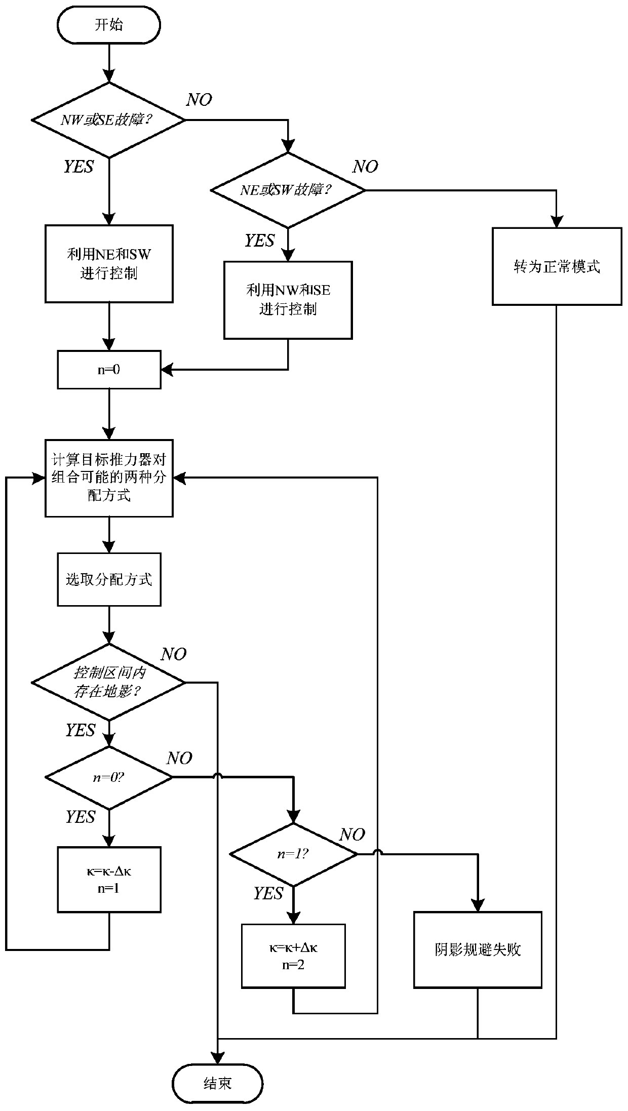
[0151] Fault judgment is carried out in (1), specifically:

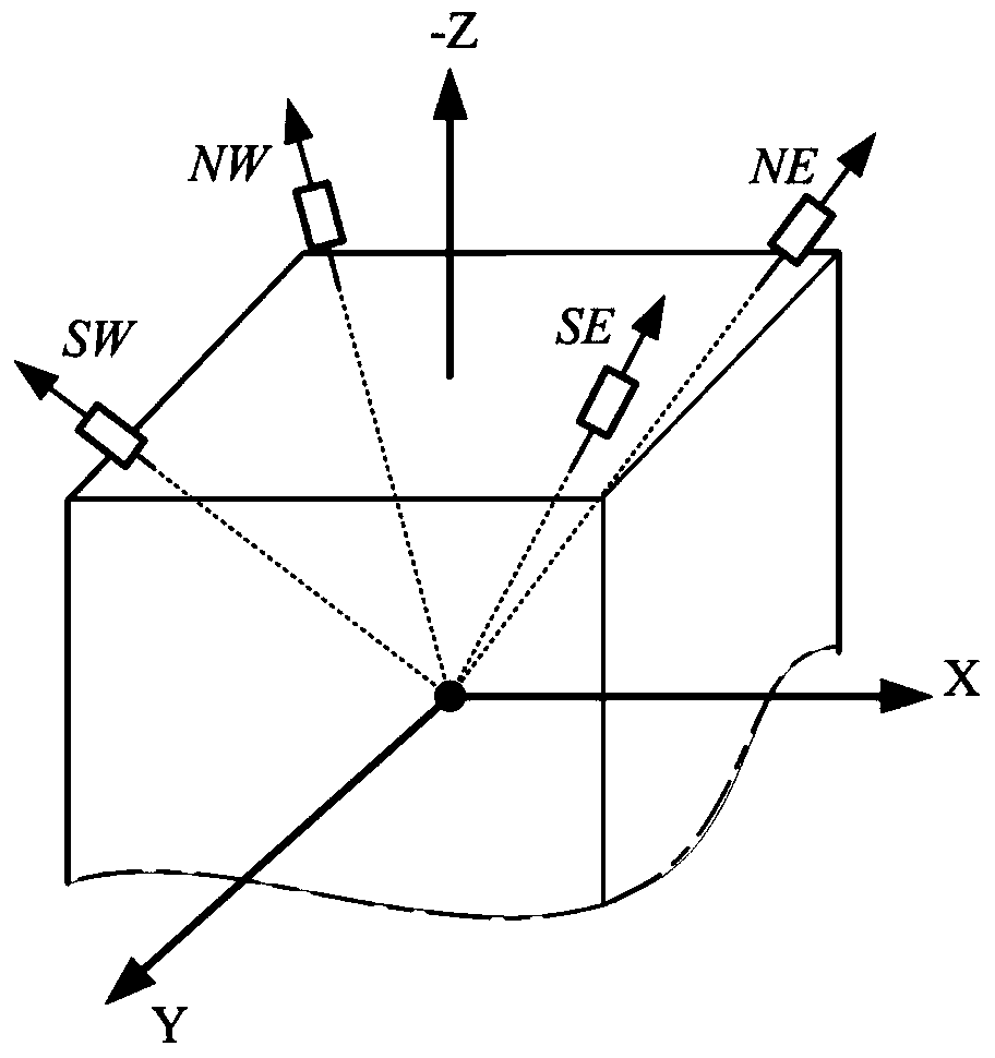
[0152] It is known that the thruster SW is faulty, and the NW and SE thruster pairs are selected for control.

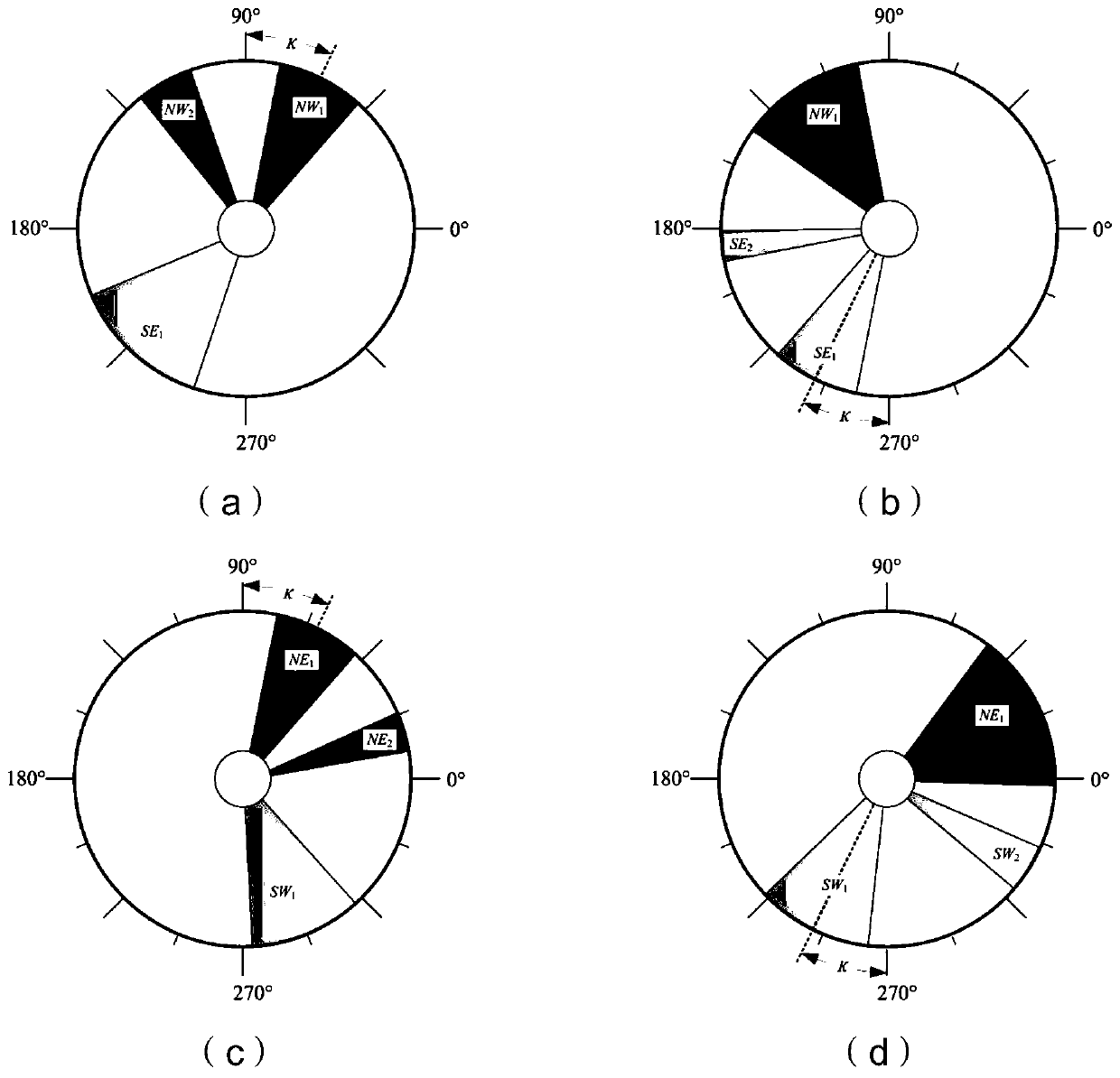
[0153] In the step (2), two possible distribution modes of the target thruster pair combination are calculated.

[0154] ①Calculate the position retention coefficient as

[0155] A 0 =0.0676

[0156] B1 0 =1.25e-4

[0157] B2 0 =2.73e-4

[0158] E. 0 =1.66e-4

[0159] The coefficients of failure mode position-holding control for NW and SE are:

[0160] A NW =A 0 , B1 NW =B1 0 , B2 NW =B2 0 ,E NW =E 0 ;

[0161] A SE =-A 0 , B1 SE =-B1 0 , B2 SE =B2 0 ,E SE =-E 0 ;

[0162] Known position holding inclination control amount di x 、di y , the position-preserving direc...

Embodiment 2

[0174] Assume that the longitude of the fixed point of the satellite is 80°E, the faulty thruster is SW, and the simulation time is 1 year. Simulation results such as Figure 4 As shown, the thruster allocation method provided by the present invention can keep the satellite within the "dead zone" range of ±0.05° of fixed-point latitude and longitude.

Embodiment 3

[0176] Set the daily east-west and north-south positions to maintain a certain amount of control, use the traditional analysis of the four orbit changes, use the optimization algorithm to perform a large number of iterations to calculate the arbitrary right ascension, the optimal four orbit changes of any jet duration, and the three times of the present invention. The thruster allocation methods generated by orbital strategy are compared, and the simulation time is 2 years. Figure 5 It is the ratio of the daily fuel consumption of the traditional 4-time orbit change distribution method and the 3-time orbit-change method in the present invention. It can be seen that the fuel consumption of the 3-time orbit-change method of the present invention is significantly smaller than that of the four-time orbit-change method. Figure 6 It is the ratio of the daily fuel consumption of the four allocation methods optimized by numerical value. It can be seen that the wall ratio is close to ...


PUM


Abstract

The invention provides an optimal thrust distribution method for position maintenance of a cone-shaped layout electric propulsion satellite in a failure mode. The method adopts an analytical method to carry out the position maintenance control allocation of an electric thruster in a cone-shaped layout failure mode. First, select a pair of thrusters that are not faulty for position keeping control according to the thrusters that have failed; then, obtain two different distribution modes of the thruster pair and select them; finally, by changing the electric thruster Avoid the shadow area at the moment of power on. The present invention adopts a completely analytical method, solves the problem of maintaining the thruster distribution in the fault mode electric propulsion position, optimizes fuel consumption, and reduces the number of thruster start-ups in the orbit cycle, so as to realize the fault mode electric propulsion position of geostationary orbit satellites Keep providing an efficient thruster distribution method.

Description

technical field [0001] The invention relates to an electric propulsion position keeping control thruster distribution method, which is mainly used on geostationary orbit satellites whose electric thrusters are in a conical layout, and is used for position keeping control thrust distribution in the case of a certain thruster failure, and belongs to Satellite attitude and orbit control technology field. Background technique [0002] For electric propulsion satellites used for geosynchronous orbit position maintenance control, the installation configuration of the electric thrusters adopts a conical layout, and four thrusters are installed in pairs and symmetrically obliquely on the four sides of the back floor. This type of thruster configuration has less redundancy. When all four thrusters can work normally, the four thrusters will spray air successively within one orbital cycle to generate the control force needed to maintain the north-south and east-west positions of the g...

Claims


Application Information

Patent Timeline
Patent Type & Authority Patents(China)
IPC IPC(8): G05B13/04B64G1/24B64G1/40B64G1/52
CPCB64G1/242B64G1/407B64G1/52B64G1/245
Inventor 马雪石恒胡少春韩冬汤亮刘潇翔陈守磊
Owner BEIJING INST OF CONTROL ENG
Why Eureka
Try Eureka