Punching and edge cutting method of conic cylindrical workpiece
A punching and cone technology, which is applied in the direction of perforating tools, manufacturing tools, metal processing equipment, etc., can solve the problems of difficult processing of holes on the thin-walled cone-shaped workpiece, and achieve simple and practical structure and simple process , Improve the effect of punching efficiency
- Summary
- Abstract
- Description
- Claims
- Application Information
AI Technical Summary
Problems solved by technology
Method used
Image
Examples
Embodiment 1
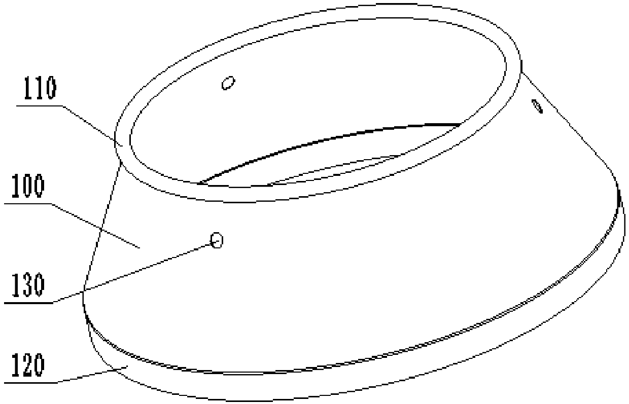
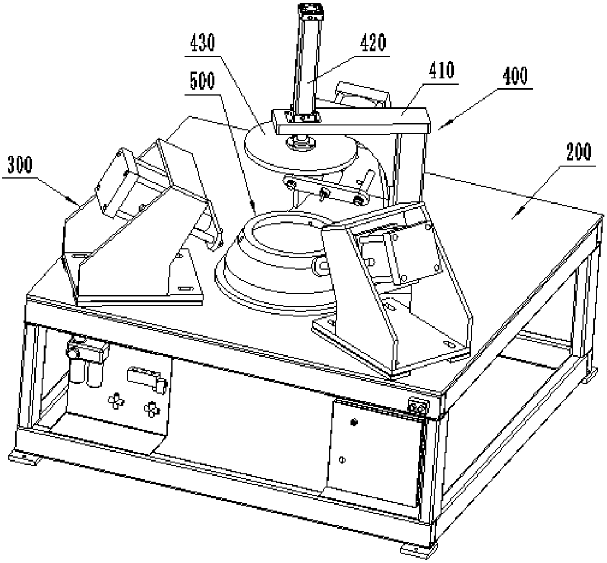
[0065] like figure 2 As shown, this embodiment is a special punching device for cone-shaped workpieces, which is mainly used for figure 1 The cone-shaped workpiece shown is punched. The cone-shaped workpiece is a thin-walled part with a wall thickness of 2 to 4mm. The edge extends vertically downward for a certain distance to form a circular edge 120 ; meanwhile, there are three holes 130 uniformly distributed along the circumferential direction on the barrel 100 . In actual production, it is necessary to process the hole 130 on the barrel 100. Due to the thin wall thickness of the workpiece, drilling with a general drilling machine will cause the edge of the hole to be depressed, the hole is not round, and the workpiece may be deformed as a whole. The problem to be solved by the embodiment.
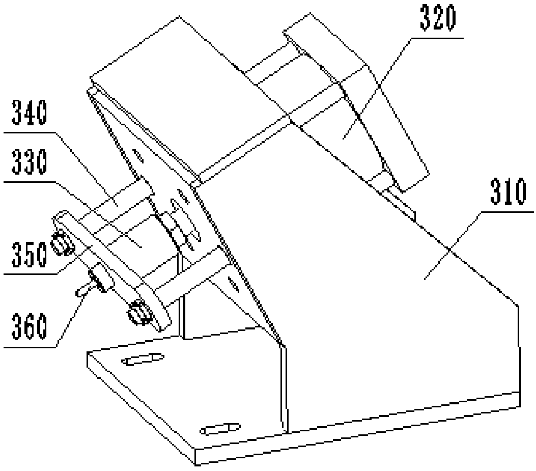
[0066] The special punching device for conical cylindrical workpieces in this embodiment includes a frame 200 , and a punching assembly 300 , a supporting mold 500 and a pressing mec...
Embodiment 2
[0072] The method for using a special punching device for a cone-shaped workpiece in this embodiment uses the special punching device for a cone-shaped workpiece in Embodiment 1 to punch the hole 130 on the cylinder body 100 of the cone-shaped workpiece, and its specific steps as follows:
[0073] First, according to the diameter of the hole 130, select the corresponding punch 360 and die sleeve, and install the punch 360 on the shaft sleeve 330, and the die sleeve is inserted into the die hole 530 of the supporting mold 500;
[0074] Secondly, the punching assembly 300 moves, the punching cylinder 320 drives the extension of the punch 360, drives the punch 360 close to the supporting die 500, adjusts the direction of the supporting die 500, and ensures that the punch 360 can be accurately inserted into the die sleeve for pre-treatment. Calibration punching accuracy;
[0075] Then, the punching assembly 300 moves, and the punching cylinder 320 drives the punch 360 to shrink, ...
Embodiment 3
[0081] In actual use, sometimes the hole 130 on the cone-shaped workpiece cylinder 100 is not punched out at one time. When the diameter of the hole 130 is large, generally the smaller hole is punched out first, and then the hole is further expanded to punch out a large hole; At this time, the three punching assemblies 300 do not work at the same time, but work in sequence. The first punching assembly 300 punches out the pin hole, the second punching assembly 300 expands the hole, and the third punching assembly 300 Used for proofreading. At this time, the workpiece needs to be rotated to the next punching assembly 300 at a certain angle after being processed by the last punching assembly 300 .
[0082]For this reason, a special punching device for cone-shaped workpieces in this embodiment is further improved on the basis of Embodiment 1, and the supporting mold 500 is fixed on the rotating disk 750, and the rotating disk 750 is installed on the rotating disk 750 through beari...
PUM
 Abstract
Description
Claims
Application Information
 - R&D
- Intellectual Property
- Life Sciences
- Materials
- Tech Scout
- Unparalleled Data Quality
- Higher Quality Content
- 60% Fewer Hallucinations
Browse by: Latest US Patents, China's latest patents, Technical Efficacy Thesaurus, Application Domain, Technology Topic, Popular Technical Reports.
© 2025 PatSnap. All rights reserved.Legal|Privacy policy|Modern Slavery Act Transparency Statement|Sitemap|About US| Contact US: help@patsnap.com


