
Optical acoustic excitation and detection integrated probe based on side edge polishing and grinding fiber grating and manufacturing method and test method of optical acoustic excitation and detection integrated probe

A technology for fiber gratings and manufacturing methods, applied in measuring devices, using optical devices to transmit sensing components, converting sensor outputs, etc., can solve problems such as large size and complex structure, and achieve large signal bandwidth, small volume, and simple production Effect

Active Publication Date: 2018-04-13
JIAXING NAJIE MICROELECTRONICS TECH
View PDF5 Cites 10 Cited by
  • Summary
  • Abstract
  • Description
  • Claims
  • Application Information

AI Technical Summary

Problems solved by technology

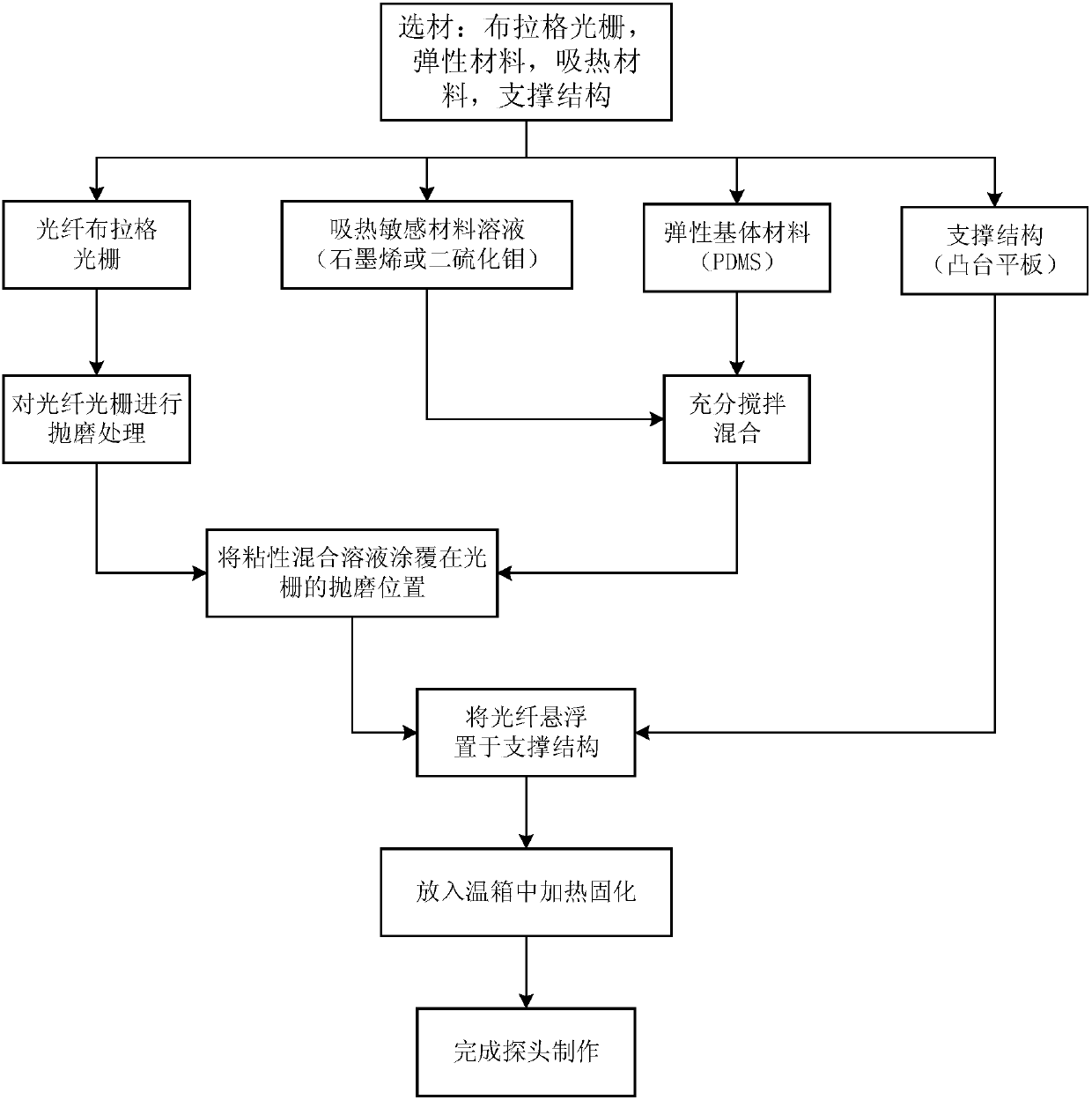
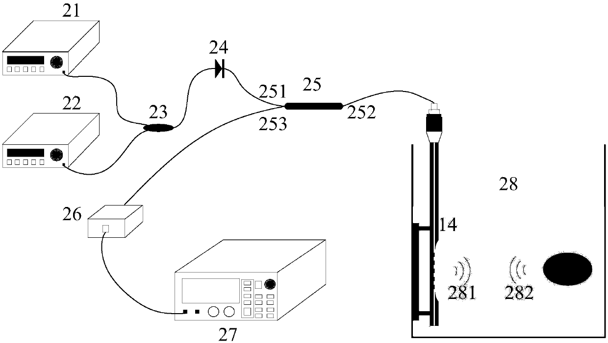
The probe is composed of a side-polished fiber Bragg grating, and the polished area of ​​the side-polished grating is coated with a mixture of elastic matrix material and heat-absorbing sensitive material, which can solve the problem of existing photoacoustic excitation. The device has the problems of complex structure and large size, and can improve the photoacoustic conversion efficiency and realize distributed detection

Method used


Image

  • Optical acoustic excitation and detection integrated probe based on side edge polishing and grinding fiber grating and manufacturing method and test method of optical acoustic excitation and detection integrated probe
  • Optical acoustic excitation and detection integrated probe based on side edge polishing and grinding fiber grating and manufacturing method and test method of optical acoustic excitation and detection integrated probe
  • Optical acoustic excitation and detection integrated probe based on side edge polishing and grinding fiber grating and manufacturing method and test method of optical acoustic excitation and detection integrated probe

Examples


Embodiment Construction

[0030] The present invention will be described in detail below in conjunction with the accompanying drawings. As a part of this description, the principle of the present invention will be described through implementation. Other aspects, features and advantages of the present invention will become clear through the detailed description.

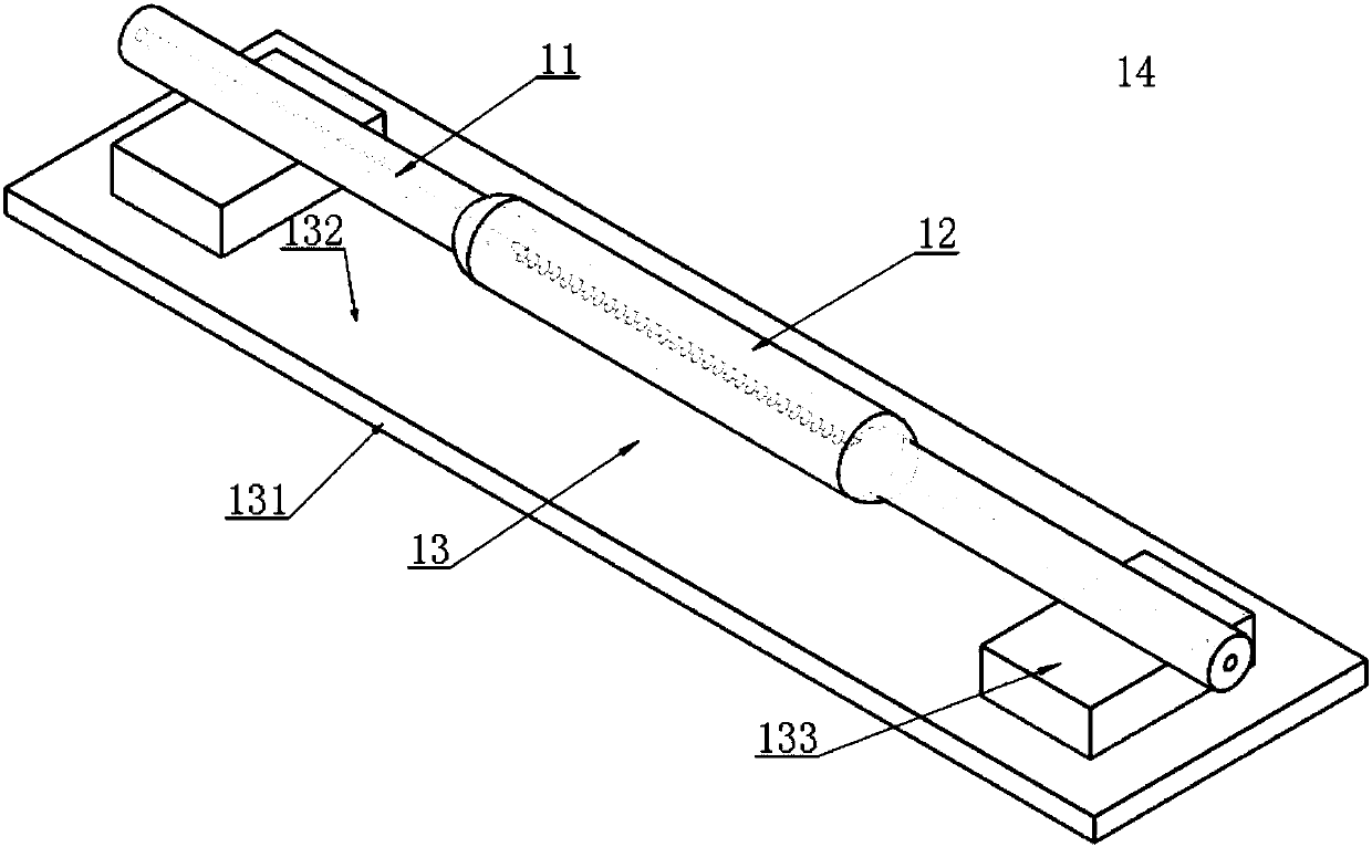
[0031] figure 1 It is a structural schematic diagram of the photoacoustic excitation and detection integrated probe based on the side-polished fiber grating of the present invention. The integrated probe 14 is mainly composed of a side-polished fiber grating 11 , a functional component 12 mixed with an elastic matrix material and an endothermic sensitive material, and a support structure 13 . The side-polished fiber grating 11 is a single-mode fiber, and its fiber grating structure is made by ultraviolet light exposure, and is made by side-polishing the grating area by means of wheel-type mechanical polishing; The functional component 12 desc...


PUM


Abstract

The invention discloses an optical acoustic excitation and detection integrated probe based on side edge polishing and grinding fiber grating and a manufacturing method and a test method of the optical acoustic excitation and detection integrated probe. A sensing unit of an optical acoustic signal excitation part is made of elastic base body materials and heat sensitive materials with high heat adsorption ability in a mixed manner and the surface of the side edge polishing and grinding fiber is coated with the sensing unit. Thus, by importing pulse laser into the sensitive materials, by use ofoptoacoustic effects, broadband acoustic signals can be excited. On the other hand, by fully using the sensitivity of the side edge polishing and grinding fiber grating to bending strain, detection of weak acoustic signals can be achieved. Thus, the probe is advantaged by simple manufacturing, small size, anti-electromagnetic interference ability, high photoacoustic energy conversion efficiency,big signal bandwidth and online distributed measurement; and meanwhile, through the small probe-type compact structure integrated with the optical acoustic excitation and detection, the probe has obvious application advantages in field of medical optoacoustic imaging, lossless detection, material science and the like.

Description

technical field [0001] The invention relates to the technical field of optical fiber sensing, in particular to a photoacoustic excitation and detection integrated probe based on side-polished optical fiber gratings, a manufacturing method and a testing method thereof. Background technique [0002] When a light beam is applied to a substance such as a solid, liquid or gas, the substance can be excited by absorbing the light energy, which is then converted (in whole or in part) into heat through a non-radiative process. If the beam is a pulsed beam or is periodically modulated, the object will produce periodic temperature changes, which will cause the material to expand with heat and contract with cold to produce periodic changes in stress and form sound waves. This phenomenon is called the photoacoustic effect (BELL A G. Upon the production and reproduction of sound bylight [J]. Journal of the Society of Telegraph Engineers, 1880, 9(34):404–426.). Since photoacoustic detecti...

Claims


Application Information

Patent Timeline
IPC IPC(8): G01D5/353
CPCG01D5/3538
Inventor 李成彭小镔张辉
Owner JIAXING NAJIE MICROELECTRONICS TECH
Learn More