
A Method of In-Machine Tool Setting for Right Angle Head of CNC Machine Tool

A technology of CNC machine tools and degree head machines, which is applied in digital control, program control, electrical program control, etc. It can solve the problems affecting the automatic processing ability of machine tools, the inability to realize tool setting in the machine, and the difficulty in using the angle head, so as to improve automation. The effect of processing capacity, improving machine tool utilization, high economic and practical value

Active Publication Date: 2020-06-16
SHENYANG LIMING AERO-ENGINE GROUP CORPORATION
View PDF10 Cites 0 Cited by
  • Summary
  • Abstract
  • Description
  • Claims
  • Application Information

AI Technical Summary

Problems solved by technology

[0002] In the field of CNC machining, in order to realize the processing of some complex parts, generally four and five coordinate machine tools are equipped with right-angle heads to expand the processing capacity of the machine tools. Since the right-angle heads are separately added machine tool accessories, they are often used correspondingly. The function is not perfect, such as the in-machine tool setting cannot be realized after the right-angle head is put on the tool, which brings difficulties to the use of the angle head, and requires the operator to measure manually and outside the machine, which not only brings quality risks to the use of the machine tool , which also affects the automatic processing capability of the machine tool and reduces the utilization rate of the machine tool

Method used


Image

  • A Method of In-Machine Tool Setting for Right Angle Head of CNC Machine Tool

Examples


Embodiment Construction

[0014] The present invention will be described in detail below in conjunction with the accompanying drawings and embodiments.

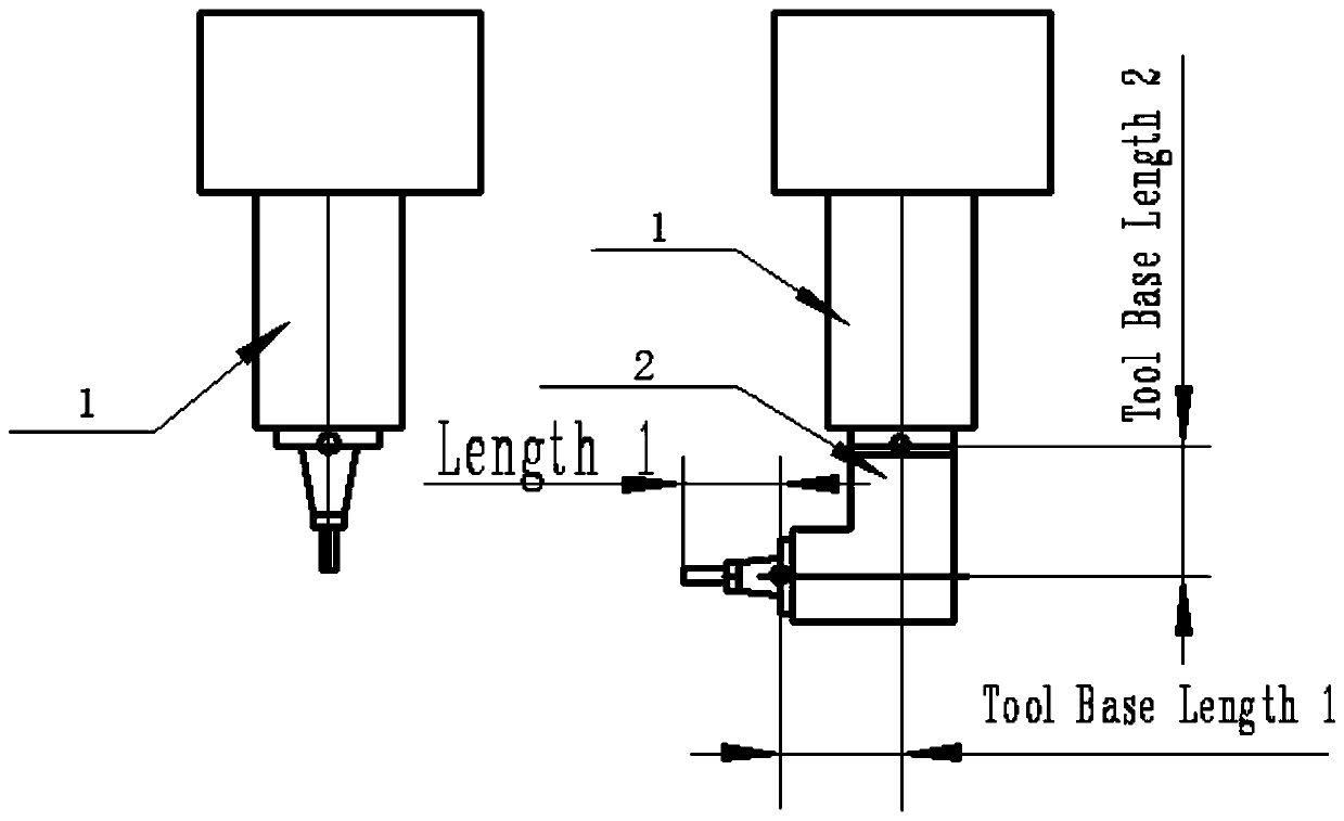
[0015] This embodiment takes the horizontal machining center of the Siemens system as an example for illustration. The program programming adopts the machine tool coordinate system. When the spindle is in a vertical state (after being suspended by 90 degrees), the clamping direction of the angle head tool is the same as that of the spindle (see figure 1 ) or vice versa. Input approximate tool length Length1 and tool radius in advance.

[0016] The steps of the right-angle head tool setting method in the machine are as follows:

[0017] The first step is to install the tool setting standard with the spindle, horizontally calibrate the position of the tool setting laser beam in the machine, and record the Y and Z coordinates of the center position of the laser beam after calibration. This position coordinate value can be passed through the tool setting...


PUM


Abstract

The invention discloses a numerical control machine tool straight angle head built-in tool setting method; the method comprises the following steps: 1, using a main shaft to mount a tool setting etalon, horizontally calibrating the built-in tool setting laser beam position, and recording the coordinate figures in the Y and Z directions of the central position of the calibrated laser beam; 2, measuring angle head related data on the main shaft, moving the cutter center on the angle head to be on the same level with the built-in tool setting laser beam through data programming, wherein certain distance is formed between the tool nose and the laser beam center; 3, correcting cutter length parameters originally set in a manual mode; 4, correcting the central height value of the originally measured angle head; 5, correcting the cutter length and radius on the angle head through corresponding cutter parameter orders. The method can improve the machine tool automation processing capability, can improve the machine tool utilization rate, can eliminate the tool setting errors, and can improve the product quality, thus providing higher economical and practical values.

Description

technical field [0001] The invention relates to the field of numerical control machining, and in particular provides an in-machine tool setting method for a right-angle head of a numerical control machine tool. Background technique [0002] In the field of CNC machining, in order to realize the processing of some complex parts, generally four and five coordinate machine tools are equipped with right-angle heads to expand the processing capacity of the machine tools. Since the right-angle heads are separately added machine tool accessories, they are often used correspondingly. The function is not perfect, such as the in-machine tool setting cannot be realized after the right-angle head is put on the tool, which brings difficulties to the use of the angle head, and requires the operator to measure manually and outside the machine, which not only brings quality risks to the use of the machine tool , It also affects the automatic processing capability of the machine tool and red...

Claims


Application Information

Patent Timeline
Patent Type & Authority Patents(China)
IPC IPC(8): G05B19/19
CPCG05B19/19G05B2219/35349
Inventor 周代忠张伟安丽莎韩永武栗生锐
Owner SHENYANG LIMING AERO-ENGINE GROUP CORPORATION
Learn More