
Preparation method of cathode for micro-electrolytic wire cutting carbon nanotube fiber tool

A technology of carbon nanotube fiber and tool cathode, which is applied in the direction of electrode manufacturing, electric processing equipment, processing electrodes, etc., can solve the problems of electrolyte update difficulty, poor processing stability, etc., and achieve strong implementability, low cost, and simple control Effect

Active Publication Date: 2019-12-06
NANJING UNIV OF AERONAUTICS & ASTRONAUTICS
View PDF7 Cites 0 Cited by
  • Summary
  • Abstract
  • Description
  • Claims
  • Application Information

AI Technical Summary

Problems solved by technology

[0005] The purpose of the present invention is to propose a method for preparing a cathode of a carbon nanotube fiber tool suitable for micro-electrolytic wire cutting in view of the problems of product discharge in the micro-processing gap of micro-electrolytic wire cutting, difficulty in electrolyte renewal, and poor processing stability.

Method used


Image

  • Preparation method of cathode for micro-electrolytic wire cutting carbon nanotube fiber tool
  • Preparation method of cathode for micro-electrolytic wire cutting carbon nanotube fiber tool
  • Preparation method of cathode for micro-electrolytic wire cutting carbon nanotube fiber tool

Examples


Embodiment Construction

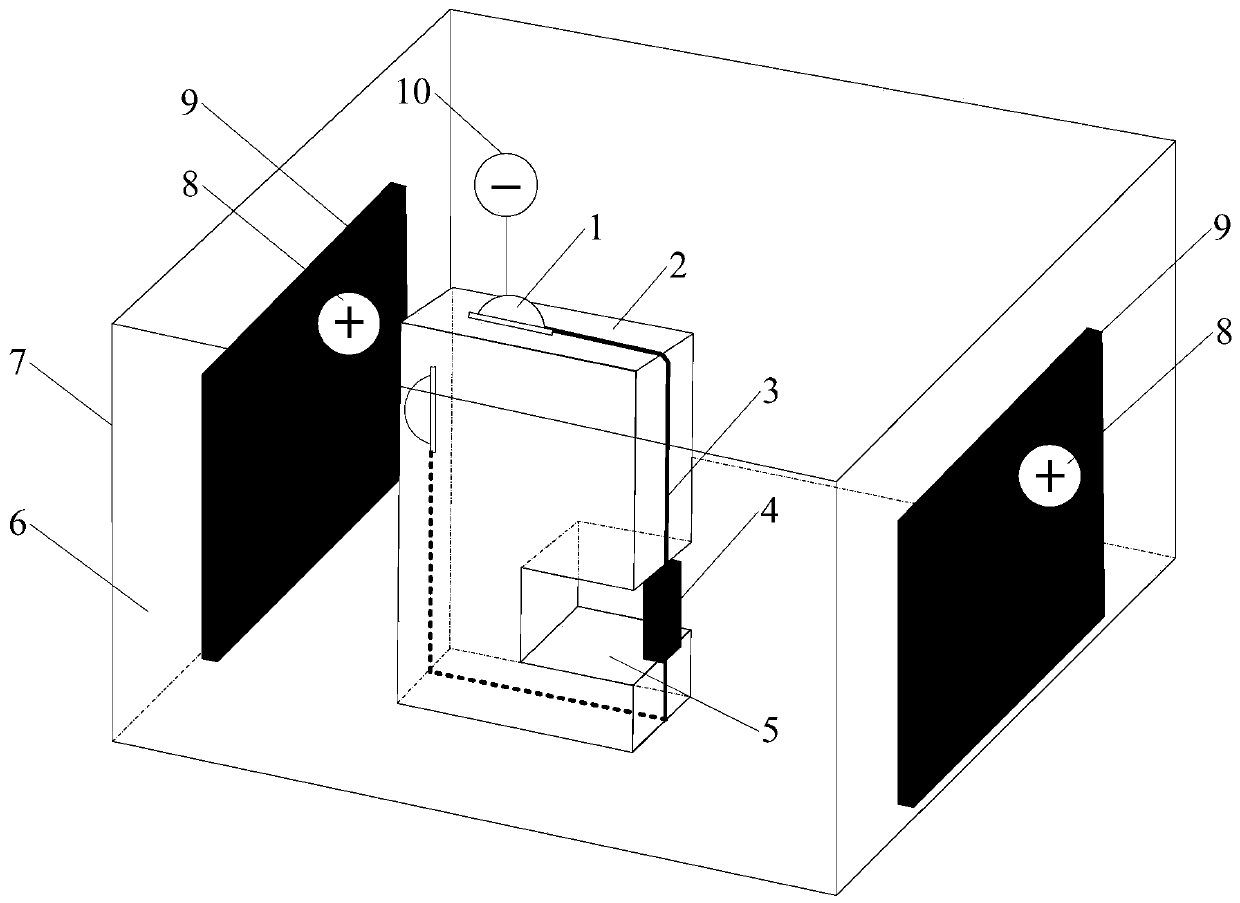
[0029] The three-dimensional motion control axes X-axis 26 , Y-axis 25 , and Z-axis 24 are installed on the machine tool body 27 , and the machine tool body 27 is fixed on the air-floating platform 18 . The three-dimensional motion control axis is controlled by the industrial computer 22 through the motion control card 23 .

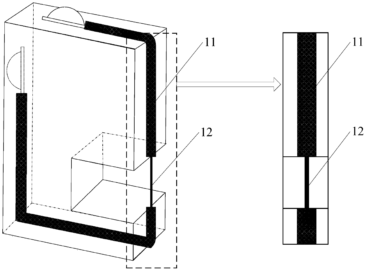
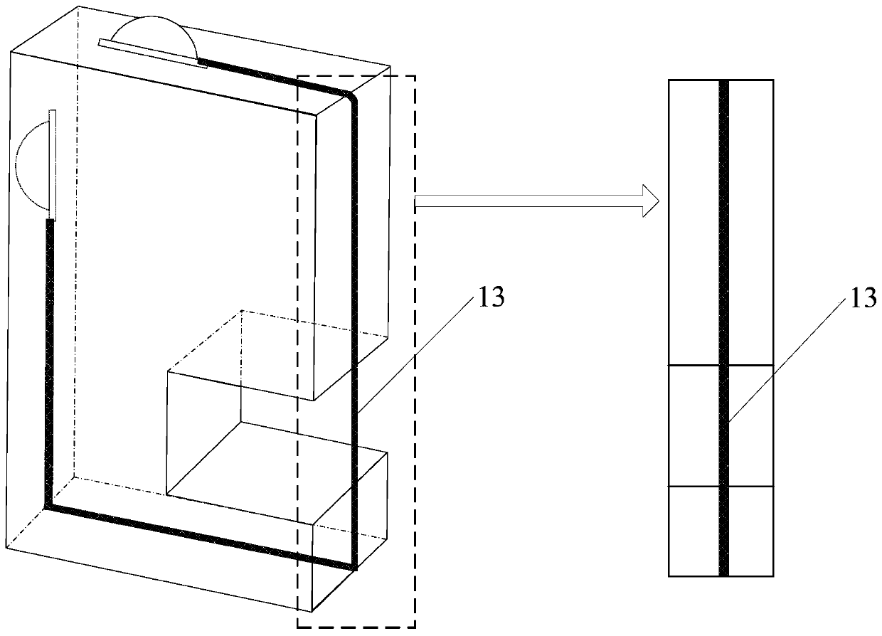
[0030] (1) Install the carbon nanotube fiber 3 on the wire electrode holder 2 and immerse it in the electroplating tank 7 filled with the electroplating solution 6 . The carbon nanotube fiber 3 is prepared by the "spinning" method of arrayed carbon nanotubes, the surface morphology is helical, and the diameter is 5-100 μm; the metal plate 9 can be silver, nickel or copper, and the electroplating solution 6 contains Metal plate 9 is a mixed solution of the same metal element ions.

[0031] (2) Connect the metal plate 9 to the positive electrode 8 of the DC power supply, connect the carbon nanotube fiber 3 to the negative electrode 10 of the DC power suppl...


PUM

PropertyMeasurementUnit
diameteraaaaaaaaaa
thicknessaaaaaaaaaa
thicknessaaaaaaaaaa

Abstract

The invention relates to a carbon nano tube fiber tool cathode suitable for micro-electrolysis linear cutting and a preparation method of carbon nano tube fiber tool cathode, and belongs to the fieldof micro electrochemical machining. The preparation method is characterized by comprising the following steps that carbon nano tube fibers are installed on a wire electrode clamp through a conductivefastening screw firstly; then, a metal is plated on a local surface or a whole surface of the original carbon nano tube fibers through a micro-electroplating method, so that the overall conductivity is improved, and the requirements of micro-electrolysis linear cutting machining are met; and finally, the excellent surface hydrophilicity of the carbon nano tube fibers and reciprocating vibration ofthe carbon nano tube fibers in a direction perpendicular to a feeding direction are utilized, so that the mass transfer rate in a micro machining gap is accelerated, and the stability and the efficiency of micro-electrolysis linear cutting machining are improved.

Description

technical field [0001] The invention relates to a method for preparing a cathode of a micro-electrolytic wire-cut carbon nanotube fiber tool, which belongs to the field of micro-electrochemical processing. Background technique [0002] Micro electrolytic wire cutting technology is a subtractive manufacturing method based on the principle of electrochemical anodic dissolution. It uses a metal wire with a diameter of several microns to tens of microns as the tool wire electrode. By combining multi-axis CNC motion, it can realize the preparation of any shape of the planar profile structure, especially suitable for micro-slits, micro-grooves and large aspect ratios. Processing of metal microstructures. Compared with other micromachining methods, microelectrolytic wire cutting technology has the characteristics of wide processing range (not limited by material strength and hardness), high efficiency, no recast layer and microcracks on the surface, and no loss of tool electrodes....

Claims


Application Information

Patent Timeline
Patent Type & Authority Patents(China)
IPC IPC(8): B23H3/04B23H3/06
CPCB23H3/04B23H3/06
Inventor 曾永彬孟岭超朱荻
Owner NANJING UNIV OF AERONAUTICS & ASTRONAUTICS
Learn More