Vertical machining center of numerical control machine tool

A vertical machining center, CNC machine tool technology, applied in metal processing, metal processing equipment, metal processing machinery parts, etc., can solve the problems of low coolant recovery rate, constant table movement, waste of resources, etc., to avoid Bad influence, avoid negative influence, effect of high work efficiency

Inactive Publication Date: 2018-04-20
郑宾玲
View PDF0 Cites 2 Cited by
  • Summary
  • Abstract
  • Description
  • Claims
  • Application Information

AI Technical Summary

Problems solved by technology

The workpiece clamping and positioning of the vertical machining center are convenient, but the movement track of the worktable is single, and the workpiece processing is not complete, which brings inconvenience to the processing of different positions of the workpiece
The vertical machining center of the usual CNC machine tool needs to use coolant in order to cool down the tool and workpiece during the machining process. At present, the recovery rate of the coolant is not high, and the debris generated during the machining process can easily fall into the slide rail. On the contrary, the movement of the workbench remains unchanged and even affects the service life of the slide rails, and the debris is not collected and recycled, resulting in a waste of resources

Method used


Image

  • Vertical machining center of numerical control machine tool
  • Vertical machining center of numerical control machine tool
  • Vertical machining center of numerical control machine tool

Examples


Embodiment Construction

[0022] The following will clearly and completely describe the technical solutions in the embodiments of the application with reference to the drawings in the embodiments of the application. Apparently, the described embodiments are only some of the embodiments of the application, not all of them.

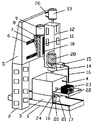
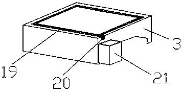
[0023] refer to Figure 1-5 , a vertical machining center of a CNC machine tool, comprising a base 1, a column 2, a workbench 3 and a closing baffle 4, the workbench 3 is placed on the top of the base 1, and the closing baffle 4 is vertically fixed on the top of the workbench 3, closed The baffle plate 4 surrounds the workbench 3 to form a cylinder structure with an upper opening. The column 2 stands vertically on both sides of the base 1. The top of the column 2 is fixedly connected with a beam 5. The cross section of the beam 5 is trapezoidal, and the beam 5 is along the opposite side of the trapezoidal slope. There is a first slide rail 6 perpendicular to the column 2, the first ...


PUM


Abstract

The application discloses a vertical machining center for a CNC machine tool, which includes a base, a column, a workbench and a closed baffle, the workbench is placed on the top of the base, the closed baffle is vertically fixed on the top of the workbench, and the closed baffle surrounds the The workbench forms a cylindrical structure with an upper opening. The uprights stand vertically on both sides of the base. The top of the uprights is fixedly connected with a beam. The cross-section of the beam is trapezoidal. A first slide block is clamped in the first slide rail, the crossbeam is connected with the transition body through the first slide block, and the top of the transition body is provided with a first servo motor. The structure of the application is simple, avoiding the negative impact of the iron filings generated during the processing and the cooling liquid used on the device and the working area, and can fully collect and recycle the iron filings generated during the processing and the cooling liquid used, It effectively saves resources and has extremely high work efficiency.

Description

technical field [0001] The present application relates to the technical field of numerical control machine tools, in particular to a vertical machining center of numerical control machine tools. Background technique [0002] The vertical machining center refers to the machining center with the main shaft in a vertical state. Its structure is mostly fixed columns, the workbench is rectangular, and there is no indexing and rotating function. It is suitable for processing discs, sleeves, and plate parts. The workpiece clamping and positioning of the vertical machining center are convenient, but the movement track of the worktable is single, and the workpiece processing is not complete, which brings inconvenience to the processing of different positions of the workpiece. The vertical machining center of the usual CNC machine tool needs to use coolant in order to cool down the tool and workpiece during the machining process. At present, the recovery rate of the coolant is not hig...

Claims


Application Information

Patent Timeline
Patent Type & Authority Applications(China)
IPC IPC(8): B23Q37/00B23Q1/01B23Q11/10B23Q11/00
CPCB23Q37/00B23Q1/015B23Q11/0046B23Q11/10
Inventor 郑宾玲
Owner 郑宾玲
Why Eureka
Try Eureka