Fermentation equipment for producing organic fertilizer from mushroom dregs
A fermentation equipment and organic fertilizer technology, which is applied in the field of enzymology or microbiology devices, can solve problems such as bacterial pollution, difficulty in the ratio of fermentation raw materials, and falling of raw materials, and achieve the effects of accurate control, reduction of bacterial pollution, and rapid speed
- Summary
- Abstract
- Description
- Claims
- Application Information
AI Technical Summary
Problems solved by technology
Method used
Image
Examples
Embodiment 1
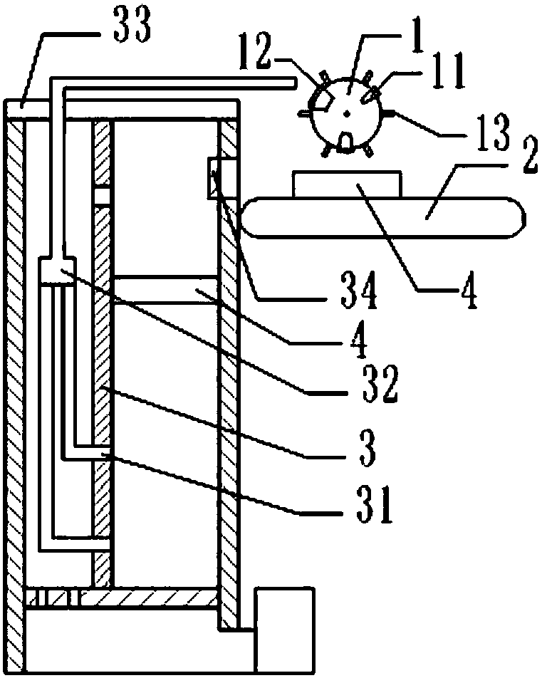
[0046] Such as figure 1 As shown, the fermentation equipment used for the production of organic fertilizer from fungus slag in this scheme includes a fermentation part and a feeding part;
[0047] The fermentation part includes a fermentation chamber and an automatic temperature and humidity measurement and adjustment system. The temperature and humidity automatic measurement and adjustment system includes an air compressor, a steam pipe, and an automatic adjustment device with heating, cooling and humidification functions; the bottom of the fermentation chamber and the temperature and humidity automatic measurement It is connected with the regulation system; the above-mentioned fermentation part is the prior art, so it will not be described in detail in this application;
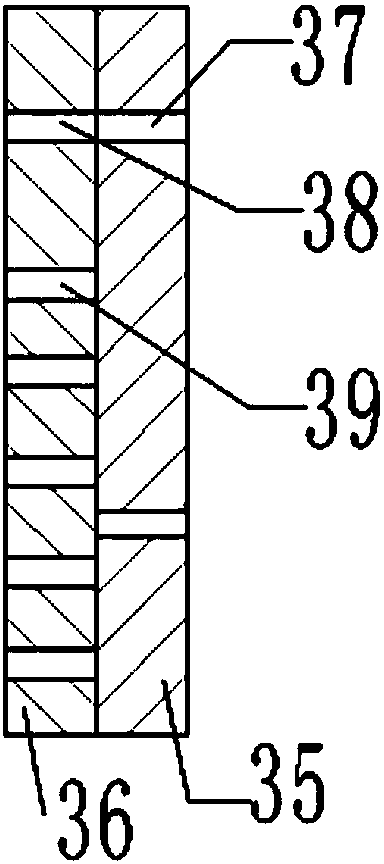
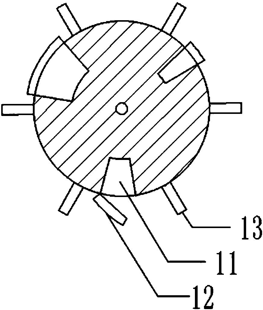
[0048] The feeding part is located on the left side of the fermentation part, including batching roller 1 and conveyor belt 2, such as image 3 Shown, the circumferential side wall of batching roller 1 is ...
Embodiment 2
[0061] The difference between this solution and Embodiment 1 is that the way the upper cover 12 opens the groove is as follows: Figure 4 As shown, the side wall of the groove 11 is provided with a slide rail, and the loam cake 12 is fixedly connected with a slide plate, and the slide plate can slide on the slide rail. The two sides of the slide plate are close to the loam cake 12, and are provided with a sprinkling opening.
[0062] When the groove 11 was at the lowest point, the upper cover 12 on the groove 11 was also at the lowest point, and the upper cover 12 and the sliding plate affixed to the upper cover 12 were subjected to gravity, so that the upper cover 12 and the sliding plate all moved along the sliding surface. The rail moves downward, and the sprinkling opening near the upper cover 12 on both sides of the sliding plate is also exposed, and the ingredients in the groove 11 are sprinkled out from the sprinkling opening; as the batching roller 1 continues to rotate...
Embodiment 3
[0064] The difference between this scheme and Embodiment 1 is that, if Figure 5 As shown, the upper cover 12 is connected to the bottom wall of the groove 11 through a tension spring.
[0065] When the groove 11 was at the lowest point, the loam cake 12 on the groove 11 was also at the lowest point, and the loam cake 12 was subjected to the action of gravity, and moved downward, and the pulling force of the extension spring was balanced with the gravity, and the loam cake 12 that descended moved the groove 11 is exposed, the ingredients in the groove 11 are scattered from the groove 11, and then as the batching roller 1 continues to rotate, the groove 11 gradually upwards, the smaller the gravity component along the tension direction of the tension spring, the tension spring will go up The cover 12 is pulled back to the surface of the groove 11 of the dispensing roller 1 .
PUM
 Abstract
Description
Claims
Application Information
 - R&D Engineer
- R&D Manager
- IP Professional
- Industry Leading Data Capabilities
- Powerful AI technology
- Patent DNA Extraction
Browse by: Latest US Patents, China's latest patents, Technical Efficacy Thesaurus, Application Domain, Technology Topic, Popular Technical Reports.
© 2024 PatSnap. All rights reserved.Legal|Privacy policy|Modern Slavery Act Transparency Statement|Sitemap|About US| Contact US: help@patsnap.com


