Transmission and automobile
A transmission and differential technology, applied in the transmission and automobile fields, can solve problems such as damage to working parts and affect the normal operation of the transmission, and achieve the effect of reducing damage
- Summary
- Abstract
- Description
- Claims
- Application Information
AI Technical Summary
Problems solved by technology
Method used
Image
Examples
Embodiment 1
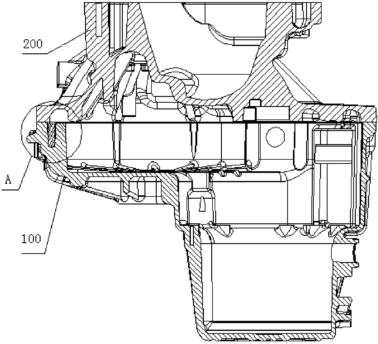
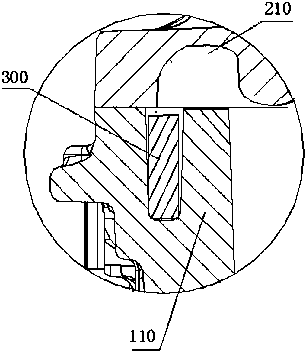
[0038] see figure 1 - Image 6 , the first embodiment provides a transmission, including a main casing 100 , a torque converter casing 200 and a magnet 300 .
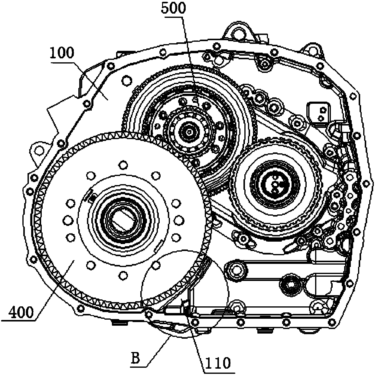
[0039] Wherein, the main housing 100 is provided with a protruding part 110, the protruding part 110 is located on the peripheral side of the differential gear 400, and the protruding part 110 is located in the working oil in the main housing 100. below the oil level.
[0040] The protruding portion 110 is provided with an accommodating groove 111 with an opening facing the torque converter housing 200, the magnet 300 is stuck in the accommodating groove 111, and the magnet 300 faces the torque converter housing One side of 200 abuts against the torque converter housing 200 .
[0041] Analyzing the structure of the above transmission, it can be seen that it is mainly composed of the main housing 100, the torque converter housing 200 and the magnet 300, wherein the main housing 100 is provided with a protruding portio...
Embodiment 2
[0046] see figure 1 - Image 6, the second embodiment provides a transmission, and also adopts the technical structural relationship of the transmission in the first embodiment above; for example: the second embodiment provides a transmission, including a main housing 100, a torque converter housing 200 and magnet 300; wherein, the main housing 100 is provided with a protruding part 110, the protruding part 110 is located on the peripheral side of the differential gear 400, and the protruding part 110 is located in the main housing The working oil in 100 is below the oil level; the protruding part 110 is provided with a receiving groove 111 opening toward the torque converter housing 200, the magnet 300 is stuck in the receiving groove 111, and the The magnet 300 is in contact with the torque converter housing 200 on a side facing the torque converter housing 200 .
[0047] The transmission provided in the second embodiment has the same main structure as the transmission in ...
Embodiment 3
[0064] Correspondingly, see figure 1 and image 3 , the third embodiment provides an automobile, which includes the transmission involved in the second embodiment above (the specific structure of the transmission will not be repeated one by one), and also includes a differential gear 400; the differential gear 400 It is located between the main casing 100 and the torque converter casing 200 of the transmission.
[0065] Obviously, the automobile provided by the third embodiment has all the advantages of the above-mentioned transmission because it includes the above-mentioned transmission, and can absorb iron filings in the working oil in the casing, reducing the damage of iron filings to other parts requiring high cleanliness.
[0066] To sum up, the embodiment of the present invention discloses a transmission and an automobile, which overcome many technical defects of the traditional transmission. The transmission and the automobile provided by the embodiments of the presen...
PUM
 Abstract
Description
Claims
Application Information
 - R&D
- Intellectual Property
- Life Sciences
- Materials
- Tech Scout
- Unparalleled Data Quality
- Higher Quality Content
- 60% Fewer Hallucinations
Browse by: Latest US Patents, China's latest patents, Technical Efficacy Thesaurus, Application Domain, Technology Topic, Popular Technical Reports.
© 2025 PatSnap. All rights reserved.Legal|Privacy policy|Modern Slavery Act Transparency Statement|Sitemap|About US| Contact US: help@patsnap.com


