Driving mechanism for reactor control rod of nuclear power plant

A technology for a nuclear power plant reactor and driving mechanism, which is applied in the control of nuclear reactions, reactors, nuclear power generation, etc., can solve the problems of low measurement accuracy of single-precision rod position detectors, poor temperature resistance of coil materials, and failure to meet single-fault criteria, etc. Achieve the effect of increasing redundant design, reducing operating current, and improving measurement accuracy and accuracy

Active Publication Date: 2018-04-20
中广核工程有限公司 +1
View PDF7 Cites 10 Cited by
  • Summary
  • Abstract
  • Description
  • Claims
  • Application Information

AI Technical Summary

Problems solved by technology

[0011] 1) There are three Ω sealing welds in total. The Ω sealing welds are thin-walled welds with a thickness of 1.9-2.3mm. Damage and leakage accidents are prone to occur in the Ω weld area, and the risk of damage and leakage is relatively high
[0012] 2) The single-precision rod position detector has low measurement accuracy and low reliability, and does not meet the single failure criterion
[0013] 3) The current of the coil is large, and the temperature resistance of the coil material is poor, so ventilation and cooling are required
[0017] 1) The Ω seal weld is located between the rod travel sleeve and the claw shell. When disassembling the claw assembly, lift the claw assembly out of the claw shell. The claw assembly contaminated by the reactor coolant is radioactive. Exposure to the environment after lifting out will cause radiation injury risk to the operator
[0018] 2) The current of the coil is large, and the temperature resistance of the coil material is poor, and ventilation and cooling are also required

Method used


Image

  • Driving mechanism for reactor control rod of nuclear power plant
  • Driving mechanism for reactor control rod of nuclear power plant
  • Driving mechanism for reactor control rod of nuclear power plant

Examples


Embodiment Construction

[0055] In order to make the purpose, technical solution and beneficial technical effects of the present invention clearer, the present invention will be further described in detail below in conjunction with the accompanying drawings and specific embodiments. It should be understood that the specific implementations described in this specification are only for explaining the present invention, not for limiting the present invention.

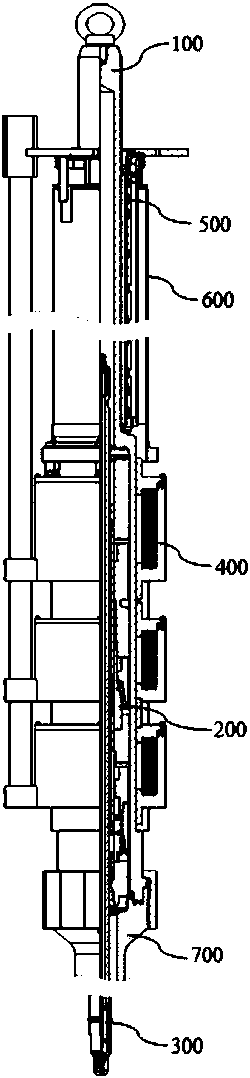
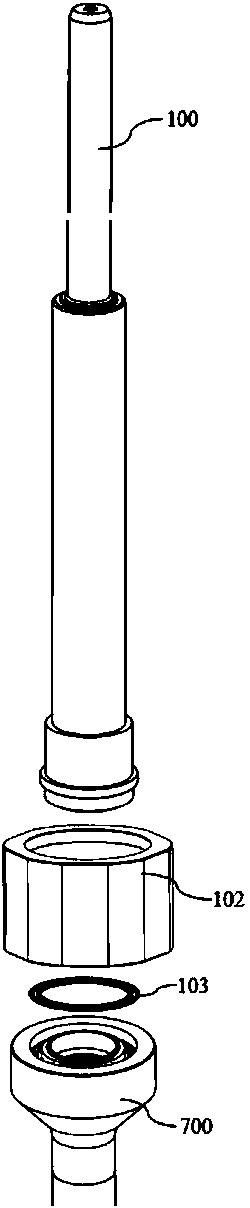
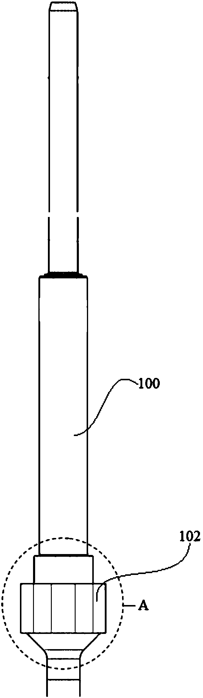
[0056] Please refer to Figures 1 to 10 As shown, the nuclear power plant reactor control rod driving mechanism of the present invention includes a pressure casing assembly 100, a claw assembly 200, a driving rod assembly 300, a coil assembly 400 and a rod position detector assembly 500, wherein the pressure casing assembly 100 is an integrated casing Body, the top is a blind pipe structure, and the bottom is detachably sealed and installed on the CRDM pipe seat of the pressure vessel top cover through a threaded connection.

[0057] Please refer...


PUM


Abstract

The invention discloses a driving mechanism for a reactor control rod of a nuclear power plant. The driving mechanism for the reactor control rod of the nuclear power plant comprises a pressure-resistant shell assembly, a falcula assembly, a driving rod assembly, a coil assembly and a rod position detector assembly, wherein the pressure-resistant shell assembly is an integrated shell, the top of the pressure-resistant shell assembly is of a blind pipe structure, and the bottom of the pressure-resistant shell assembly is connected by virtue of a screw thread and is detachably arranged on a CRDMpipe socket of a pressure vessel head in a sealing manner. Compared with the prior art, the driving mechanism for the reactor control rod of the nuclear power plant adopts the integrated pressure-resistant shell assembly, no weld joint is formed on the pressure-resistant shell assembly, and the pressure-resistant shell assembly and the CRDM pipe socket are connected by adopting the screw thread and are sealed by virtue of a pair of sealing rings, so that the risk of reactor coolant leakage can be effectively reduced. Besides, the falcula assembly adopts a double-tooth falcula structure, the wear resistance of a falcula can be greatly improved, the service life of a control rod driving mechanism is prolonged, the falcula assembly is assembled and disassembled from the bottom of the pressure-resistant shell assembly, and irradiation injury risk produced to operating personnel can be reduced.

Description

technical field [0001] The invention belongs to the field of pressurized water reactor nuclear power plants, and more specifically, the invention relates to a driving mechanism for control rods of nuclear power plant reactors. Background technique [0002] The Control Rod Drive Mechanism (CRDM for short) is a vertical step-by-step magnetic lifting device installed on the top cover of the reactor pressure vessel. As an important device for implementing reactivity control, CRDM can drive the control rod assembly to move up and down within the core range according to the command, and keep it at the command height, or the control rod can be inserted into the core under the action of gravity to control the start-up of the reactor. , power regulation and shutdown functions. In addition, the CRDM pressure vessel, as the primary circuit pressure boundary in contact with the coolant, is a safety barrier for radioactive containment. [0003] At present, the commonly used CRDM mainly...

Claims


Application Information

Patent Timeline
Patent Type & Authority Applications(China)
IPC IPC(8): G21C7/12G21C9/02
CPCG21C7/12G21C9/02Y02E30/30
Inventor 李跃忠赵毛毛张飞吴和北魏乔苑刘言午冉小兵董杨张逸飞
Owner 中广核工程有限公司
Why Eureka
Try Eureka