
Wastewater treatment device for polyester yarn spinning production

A wastewater treatment and yarn technology, which is applied in the field of polyester yarn production, can solve the problems of dye wastewater discharge up to standard, difficult biochemical degradation, etc., and achieve the effect of avoiding waste of resources

Inactive Publication Date: 2018-04-24
YANCHENG ZHONGLI TEXTILE CO LTD
View PDF0 Cites 0 Cited by
  • Summary
  • Abstract
  • Description
  • Claims
  • Application Information

AI Technical Summary

Problems solved by technology

[0002] A very important step in the production of polyester yarn is to dye the yarn. Because the dye wastewater has high COD, high chroma, and high salt content, organic matter is difficult to biodegrade, and the water quality and volume change greatly with time (wastewater indirect Discharge) and other characteristics, dye wastewater has become a difficult point in the field of industrial wastewater treatment; dye wastewater treatment includes various methods, according to different treatment principles, the treatment methods can be mainly divided into physical methods, chemical methods and biological methods. In practical applications, A single treatment method is often unable to discharge dye wastewater up to the standard, and several methods are generally used for joint treatment; the current treatment process has gradually shifted to a mixed multi-stage treatment process with anaerobic-aerobic combined treatment as the axis and a combination of physical, chemical or chemical methods. , in order to achieve the best treatment effect; however, the microorganisms of the anaerobic-aerobic combined treatment method have certain requirements on nutrients, temperature, and pH value. The advantages of high removal rate and stable effect still make it occupy an important position in the treatment of dye wastewater

Method used

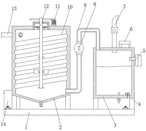
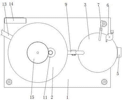

Image

  • Wastewater treatment device for polyester yarn spinning production
  • Wastewater treatment device for polyester yarn spinning production

Examples


Embodiment Construction

[0018] The following will clearly and completely describe the technical solutions in the embodiments of the present invention with reference to the accompanying drawings in the embodiments of the present invention. Obviously, the described embodiments are only some, not all, embodiments of the present invention.

[0019] refer to Figure 1-2 , a wastewater treatment device for polyester yarn textile production, comprising a base 1, the upper surface of the base 1 is welded with a first reaction barrel 2 and a second reaction barrel 3, and the first reaction barrel 2 is far away from the second reaction barrel 3 The side outer wall is welded with a medicine tube 13 close to the bottom end, and the top inner wall of the first reaction barrel 2 is reserved with a sinking groove with an opening downward, and the bottom end of the sinking groove is connected with a transmission rod 12 in rotation, and the top circumference outer wall of the transmission rod 12 is keyed. Connected w...


PUM


Abstract

The invention discloses a wastewater treatment device for polyester yarn textile production, which comprises a base, a first reaction barrel and a second reaction barrel are welded on the upper surface of the base, and the side of the first reaction barrel is away from the second reaction barrel The outer wall is welded near the bottom end with a chemical tube, the top inner wall of the first reaction barrel is reserved with a sinking tank with an opening downward, and the bottom end of the sinking tank is rotatably connected to a transmission rod, and the outer wall of the top circumference of the transmission rod is keyed. There is a driven gear, the top of the first reaction barrel close to the side of the driven gear is fixed with a motor by bolts, and the top of the output shaft of the motor is welded with a driving gear which meshes with the driven gear. The invention can accelerate the flow of the internal liquid when the grid plate rotates, fully mix the chemical agent and waste water to make the chemical reaction more efficient, and prevent the product from sticking to the inner wall of the reaction tank, so as to ensure that the inner wall of the reaction tank is smooth and convenient for later stage. cleaning.

Description

technical field [0001] The invention relates to the technical field of polyester yarn production, in particular to a wastewater treatment device for polyester yarn textile production. Background technique [0002] A very important step in the production of polyester yarn is to dye the yarn. Because the dye wastewater has high COD, high chroma, and high salt content, organic matter is difficult to biodegrade, and the water quality and volume change greatly with time (wastewater indirect Discharge) and other characteristics, dye wastewater has become a difficult point in the field of industrial wastewater treatment; dye wastewater treatment includes various methods, according to different treatment principles, the treatment methods can be mainly divided into physical methods, chemical methods and biological methods. In practical applications, A single treatment method is often unable to discharge dye wastewater up to the standard, and several methods are generally used for joi...

Claims


Application Information

Patent Timeline
IPC IPC(8): C02F9/04C02F103/30
CPCC02F1/52C02F1/76C02F2103/30
Inventor 高翠
Owner YANCHENG ZHONGLI TEXTILE CO LTD
Learn More