Rocking kiln

A kiln and kiln barrel technology, applied in the field of calcination equipment, can solve the problems of high energy consumption, uneven heating of materials, short temperature control time, etc., and achieve the effect of simple material recovery, saving the cost of dust recovery and processing, and low cost

Pending Publication Date: 2018-04-24
山东优益环保设备有限公司
View PDF7 Cites 1 Cited by
  • Summary
  • Abstract
  • Description
  • Claims
  • Application Information

AI Technical Summary

Problems solved by technology

[0003] The purpose of the present invention is to provide a left and right swing type kiln aiming at the technical defects of the prior art, so as to solve the technical difficulties of low temperature control accuracy and short temperature control time of the rotary kiln in the prior art
[0004] Another technical problem to be solved by the present invention is the problem of overheating in the recovery process of calcined materials in the rotary kiln in the prior art
[0005] Another technical problem to be solved by the present invention is that in the prior art, the materials in the shuttle kiln, roller kiln, tunnel kiln, etc. are easily heated unevenly, and the energy consumption is relatively high.

Method used


Image

  • Rocking kiln

Examples


Embodiment 1

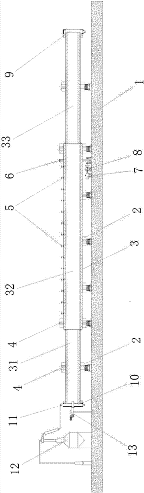
[0021] A swing kiln, including base 1, supporting wheel 2, kiln shell 3, rolling ring 4, burner 5, ring gear 6, motor 7, reducer 8, discharge end cover 9, feed end cover 10 , smoke outlet 11, dust collector 12, screw feeder 13, wherein the kiln shell 3 is composed of a preheating section 31, a firing section 32, and a cooling section 33 connected end to end in sequence, and a number of supporting wheels are arranged on the abutment 1 2. There are several rolling rings 4 on the outer wall of the kiln shell 3, the kiln shell 3 is connected to several supporting wheels 2 through several rolling rings 4, each rolling ring 4 corresponds to a supporting wheel 2, and the firing section The side wall of 32 is provided with several burners 5, and the outer wall of described firing section 32 has ring gear 6, and motor 7 is positioned at abutment 1, and described motor 7 is connected with described ring gear 6 through speed reducer 8, The tail end of the cooling section 33 is connected ...

Embodiment 2

[0029] A swing kiln, including base 1, supporting wheel 2, kiln shell 3, rolling ring 4, burner 5, ring gear 6, motor 7, reducer 8, discharge end cover 9, feed end cover 10 , smoke exhaust port 11, dust collector 12, screw feeder 13, wherein the kiln shell 3 is composed of a preheating section 31, a firing section 32, and a cooling section 33 connected end to end in sequence, and a number of supporting wheels are arranged on the base 1 2. There are several rolling rings 4 on the outer wall of the kiln shell 3, the kiln shell 3 is connected to several supporting wheels 2 through several rolling rings 4, each rolling ring 4 corresponds to a supporting wheel 2, and the firing section The side wall of 32 is provided with several burners 5, and the outer wall of described firing section 32 has ring gear 6, and motor 7 is positioned at base 1, and described motor 7 is connected with described ring gear 6 through speed reducer 8, The tail end of the cooling section 33 is connected wi...


PUM


Abstract

The invention provides a rocking kiln arranged in the shape of an inclined barrel and driven by a driving mechanism to rotate and rock side to side; material enters from a feed end that is high, to bespecific, the material rolls along the periphery and moves axially toward a discharge end that is low. Burners and nozzles may be arranged radially in the middle of the kiln where the material is calcined and heated, and heat that is generated may be transmitted from the middle of the kiln to a head of the kin and is finally guided into a dust remover for centralized treatment. According to the technical scheme, a calcining portion is arranged in the middle of a kiln barrel; flexible adjustments can be made according to kiln length during calcining; a thermocouple has higher temperature control precision; zonal control can be provided so that control precision for a material heating process curve is increased to + / - 2 DEG; waste gas is guided out of the head, centralized collection of thewaste gas is achieved, and raw material that is not heated can be preheated to certain degree; the calcining process is accompanied by roll-conveying of the material, the heating mode is more uniform, and energy utilization rate is increased.

Description

technical field [0001] The invention relates to the technical field of calcination equipment, in particular to a swing kiln. Background technique [0002] A kiln is an industrial device used to perform calcination operations. The kilns used for calcination of powder or particles in the prior art mainly include rotary kilns, shuttle kilns, roller kilns, tunnel kilns, etc. Among them, shuttle kiln, roller kiln, tunnel kiln and other structures are relatively simple, but they need bowl-shaped containers. During the calcination process, the materials are not heated uniformly, and problems such as undercooking and over-burning are prone to occur. Relatively speaking, the application of rotary kiln is more common. Its main structure includes an inclined and horizontal rotary cylinder. Raw meal powder is fed from the higher end, and fuel is burned at the lower end. The material is heated while moving, so as to play a role. The role of calcination. Although the problem of uneven h...

Claims


Application Information

Patent Timeline
Patent Type & Authority Applications(China)
IPC IPC(8): F27B7/12F27B7/34F27B7/22F27B7/32
CPCF27B7/12F27B7/22F27B7/3205F27B7/34
Inventor 王延兵
Owner 山东优益环保设备有限公司
Why Eureka
Try Eureka