
Magnetic field coupling type and electric field coupling type-combined wireless electric energy transmission system

A technology of wireless energy transmission and electric field coupling, applied in the direction of electrical components, circuit devices, etc., can solve the problems of large voltage stress of passive resonant components, unfavorable safety work of coupling mechanism, and increase system security issues, so as to improve system security, The effect of reducing the number of components and improving the utilization of components

Inactive Publication Date: 2018-04-24
SOUTHWEST JIAOTONG UNIV
View PDF4 Cites 13 Cited by
  • Summary
  • Abstract
  • Description
  • Claims
  • Application Information

AI Technical Summary

Problems solved by technology

For the electric field coupled wireless power transfer system, the lower plate equivalent capacitance usually requires a larger inductance to compensate, and the inductance with a larger inductance is generally difficult to manufacture, thus increasing the production cost
At the same time, the higher switching frequency of the system makes the passive resonant components bear greater voltage stress, which increases the safety problem of the system
[0006] Whether it is a magnetic field coupling type or an electric field coupling type wireless power transfer system, they have only one coupling mechanism. When this coupling mechanism transmits high-power electric energy, the coupling coil or coupling plate must bear relatively large power alone, which is not conducive to Coupling mechanism continues to work safely

Method used


Image

  • Magnetic field coupling type and electric field coupling type-combined wireless electric energy transmission system
  • Magnetic field coupling type and electric field coupling type-combined wireless electric energy transmission system
  • Magnetic field coupling type and electric field coupling type-combined wireless electric energy transmission system

Examples


Embodiment Construction

[0026] Below in conjunction with accompanying drawing, the specific embodiment of the present invention and working principle are described in further detail:

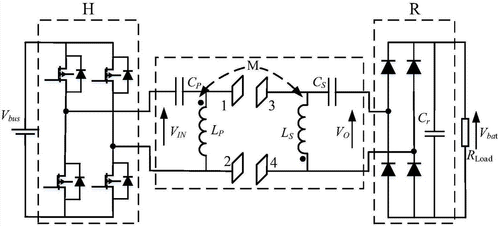
[0027] Such as figure 1 As shown, a wireless power transmission system combining a magnetic field coupling type and an electric field coupling type includes a pre-stage circuit part, an intermediate circuit part, and a post-stage circuit part;

[0028] The front-stage circuit part is mainly composed of a DC power supply and a high-frequency inverter circuit H, and the DC power supply supplies a DC voltage V bus , the DC voltage is converted into a high-frequency AC voltage V through a high-frequency inverter circuit IN , V IN is the AC input voltage of the intermediate circuit;

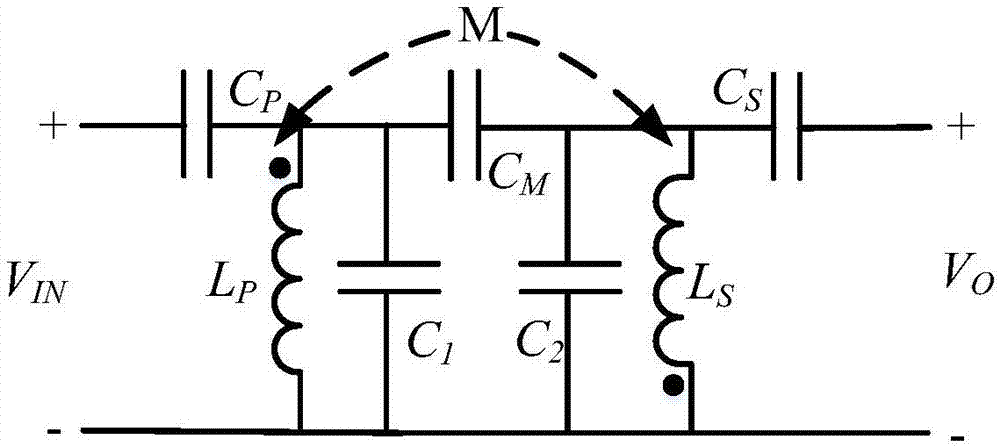
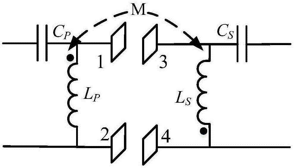
[0029] The intermediate circuit part is mainly composed of the transmitter compensation capacitor C P , Transmitter coupling inductance L P , Transmitter plate 1, Transmitter plate 2, Receiver compensation capacitor C S , Receiver coupli...


PUM


Abstract

The invention discloses a magnetic field coupling type and electric field coupling type-combined wireless electric energy transmission system. One output end of a high-frequency inverter circuit H isconnected with a first transmitting end polar plate through a transmitting end compensation capacitor CP, and the other output end of the high-frequency inverter circuit H is connected with a second transmitting end polar plate; the same-name end of a transmitting end coupling inductor LP is connected with the first transmitting end polar plate, and the different-name end of the transmitting end coupling inductor LP is connected with the second transmitting end polar plate; one input end of a rectifier circuit R is connected with a first receiving end polar plate through a receiving end compensation capacitor CS, and the other input end of the rectifier circuit R is connected with a second receiving end polar plate; the different-name end of a receiving end coupling inductor LS is connected with the first receiving end polar plate, and the same-name end of the receiving end coupling inductor LS is connected with the second receiving end polar plate; the second transmitting end polar plate is coupled to the second receiving end polar plate; and the transmitting end coupling inductor LP is coupled to the receiving end coupling inductor LS. The system has the advantages of increased transmission capacity, improved safety, structural simplicity, and improved utilization ratio of components.

Description

technical field [0001] The invention relates to the field of wireless power transmission, in particular to a wireless power transmission system combining magnetic field coupling and electric field coupling. Background technique [0002] Wireless power transmission technology provides flexible, safe and reliable power supply to electrical appliances in a non-contact manner, avoiding the safety problems of contact sparks and leakage in traditional plug-in power transmission systems, and solving the problem that wires cannot be used in some occasions. Problem with electrical connection. The technology is already widely used in built-in medical devices, consumer electronics, lighting and electric vehicles. [0003] At present, there are two types of wireless power transmission technologies: magnetic field coupling and electric field coupling. Magnetic field coupled wireless power transfer technology has been studied a lot at home and abroad. This technology is relatively matur...

Claims


Application Information

Patent Timeline
Patent Type & Authority Applications(China)
IPC IPC(8): H02J50/12H02J50/05H02J50/40
CPCH02J50/12H02J50/05H02J50/40
Inventor 麦瑞坤罗博龙涛
Owner SOUTHWEST JIAOTONG UNIV
Learn More