Shock absorber scrap iron automatic adsorption device
A technology of adsorption device and shock absorber, applied in chemical instruments and methods, removal of smoke and dust, cleaning methods and utensils, etc. The risk of abnormal noise, the effect of helping foreign matter adsorption and avoiding secondary pollution
- Summary
- Abstract
- Description
- Claims
- Application Information
AI Technical Summary
Problems solved by technology
Method used
Image
Examples
Embodiment 1
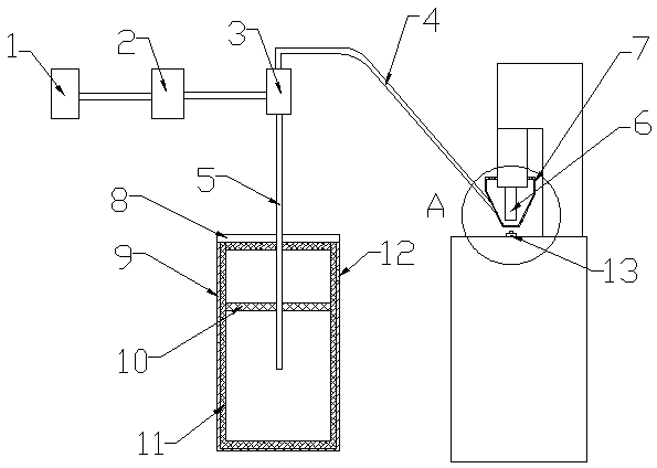
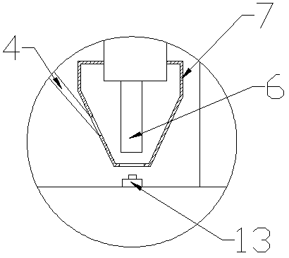
[0034] like Figure 1-2 As shown, an automatic adsorption device for shock absorber iron filings includes an air pump 1, a pneumatic conveyor 3, a suction cover 7 and a storage device, one end of the pneumatic conveyor 3 is connected to the first air pipe 4, and the other end is connected to the second air pipe 5. The first air pipe 4 is connected to the suction cover 7, the second air pipe 5 is connected to the storage device, the pneumatic conveyor 3 is connected to the air pump 1 through the solenoid valve 2, and the suction cover 7 is sleeved on the Outside the riveting head 6, the suction cover 7 is a tapered structure with a narrow bottom and a wide top. The lower end of the riveting head 6 is located in the suction cover 7, and is about 5mm from the lower end of the suction cover 7. The specific distance can be adjusted according to the riveted products of each production line, the first air pipe 4 and the second air pipe 5 are plastic hoses, the riveting head 6 is a ri...
Embodiment 2
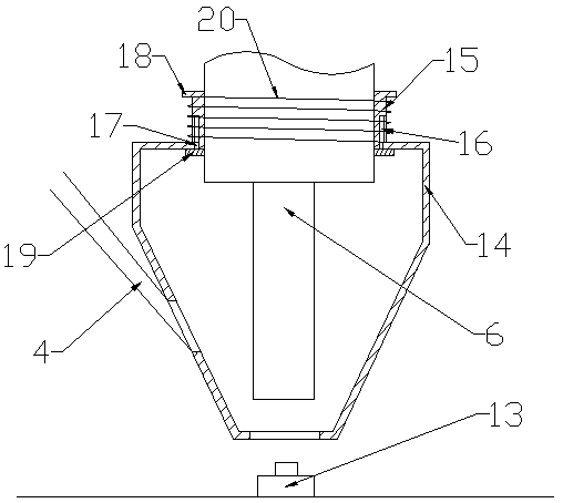
[0038] This embodiment is basically the same as Embodiment 1, the difference is: as image 3As shown, the suction cover is sleeved on the outside of the riveting head 6, and the suction cover includes a cover body 14 with openings at both ends and a connecting ring 15 arranged at the opening at the upper end of the cover body 14. The connecting ring 15 The side wall is symmetrically provided with a vertical chute 16, and the upper opening of the cover body 14 is provided with a slider 17 matched with the chute, the upper end of the chute is closed, and the lower end is an open structure, and the connecting ring 15 The upper end of the upper end is provided with an upper limit plate 18, and the lower end is fixedly connected with a lower limit plate 19 by screws. The connecting ring 15 and the upper limit plate 18 are integrally structured. The upper cover is equipped with a compression spring 20 .
[0039] The cover body 14 is a tapered transparent structure with a narrow bot...
Embodiment 3
[0042] This embodiment is basically the same as Embodiment 1 or Embodiment 2, except that: Figure 4 and Figure 5 As shown, the storage device includes a storage box, the storage box includes an outer box 21 and an inner box 22, the front end of the outer box 21 is hinged with a door, the door is provided with a handle, the outer box Both sides of box body 21 are provided with a plurality of exhaust outlets 12, and the inner wall of described outer box body 21 is pasted with muffler device 11, and described muffler device 11 is plastic foam or muffler cotton, and inside of described outer box body 21 The bottom end is provided with an electromagnet 23, and the electromagnet 23 is connected with a power source.
[0043] The lower end of the inner box body 22 is provided with a groove that matches the electromagnet 23, and the upper end of the inner box body 22 is provided with a box cover, and the box cover includes a middle ring 24, an outer ring 25 and is arranged on the T...
PUM
 Abstract
Description
Claims
Application Information
 - R&D
- Intellectual Property
- Life Sciences
- Materials
- Tech Scout
- Unparalleled Data Quality
- Higher Quality Content
- 60% Fewer Hallucinations
Browse by: Latest US Patents, China's latest patents, Technical Efficacy Thesaurus, Application Domain, Technology Topic, Popular Technical Reports.
© 2025 PatSnap. All rights reserved.Legal|Privacy policy|Modern Slavery Act Transparency Statement|Sitemap|About US| Contact US: help@patsnap.com


