
Electrochemical machining device

A processing device and workbench technology, which is applied in the field of mechanical processing, can solve the problems of uncontrollable processing distance, large material loss, rough surface, etc., and achieve the effects of improving the scrap rate, overcoming easy blockage or damage, and overcoming the inability to adjust the height

Inactive Publication Date: 2018-04-27
青岛卫辽医用生物材料有限公司
View PDF8 Cites 0 Cited by
  • Summary
  • Abstract
  • Description
  • Claims
  • Application Information

AI Technical Summary

Problems solved by technology

[0002] The traditional micro-tip machining method is mechanical grinding, but the surface of mechanical grinding is relatively rough, and the material loss is relatively large for wire processing needle tips with a diameter of less than 0.5mm. Electrochemical machining is also called electrochemical machining (Electrochemical Machining, ECM) It is a processing method that uses the principle of electrochemical anodic dissolution to remove materials. Electrolytic processing has high processing speed, high processing precision, good surface quality, no heat-affected layer, no macro cutting force, no loss of tool cathode and is not affected by material strength, toughness, The limitation of hardness and other advantages, but ordinary electrolysis or electric spark can not control such a fine processing distance or produce such a fine cathode needle tip with a diameter of less than 0.5mm. In the prior art, for example, the utility model patent with application number 201521067044.2 includes control cabinets, Spindle motor, bracket, electrolyte tank, base, the bracket is connected to the base, the spindle motor is set on the top of the bracket, the output shaft of the spindle motor is connected with the screw rod installed on the bracket through a coupling, and the sliding table is sleeved on the screw rod. And screwed with the screw rod, the sliding table is set on the guide rail parallel to the screw rod on the bracket at the same time, the autorotation motor is fixedly connected with the sliding table, the workpiece chuck is connected with the output shaft of the autorotation motor through a coupling, and the workpiece is installed on the workpiece chuck On the top, the anode is connected with the axis of the rotation motor, the electrolyte tank is set on the magnetic stirrer on the base, the cathode ring is installed in the electrolyte tank, and the upper limit block and the lower limit block are arranged on the guide rail. Although the structure of the invention is simple, but There are many deficiencies and defects. In the existing equipment, there are defects in the design of the anode interface. The top of the anode interface is not equipped with an electrolyte storage and sealing device, and there is no structure for cleaning the milling cutter with a brush. In view of these situations, In order to avoid the above-mentioned technical problems, it is necessary to provide an electrolytic machining device to overcome the defects in the prior art

Method used


Image

  • Electrochemical machining device
  • Electrochemical machining device
  • Electrochemical machining device

Examples


Embodiment Construction

[0014] The technical solutions in the embodiments of the present invention will be clearly and completely described below in conjunction with the accompanying drawings in the embodiments of the present invention. Obviously, the described embodiments are only a part of the embodiments of the present invention, rather than all the embodiments. Based on the embodiments of the present invention, all other embodiments obtained by those of ordinary skill in the art without creative work shall fall within the protection scope of the present invention.

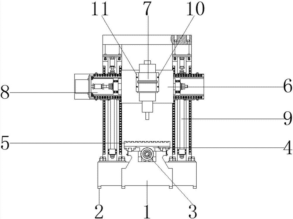
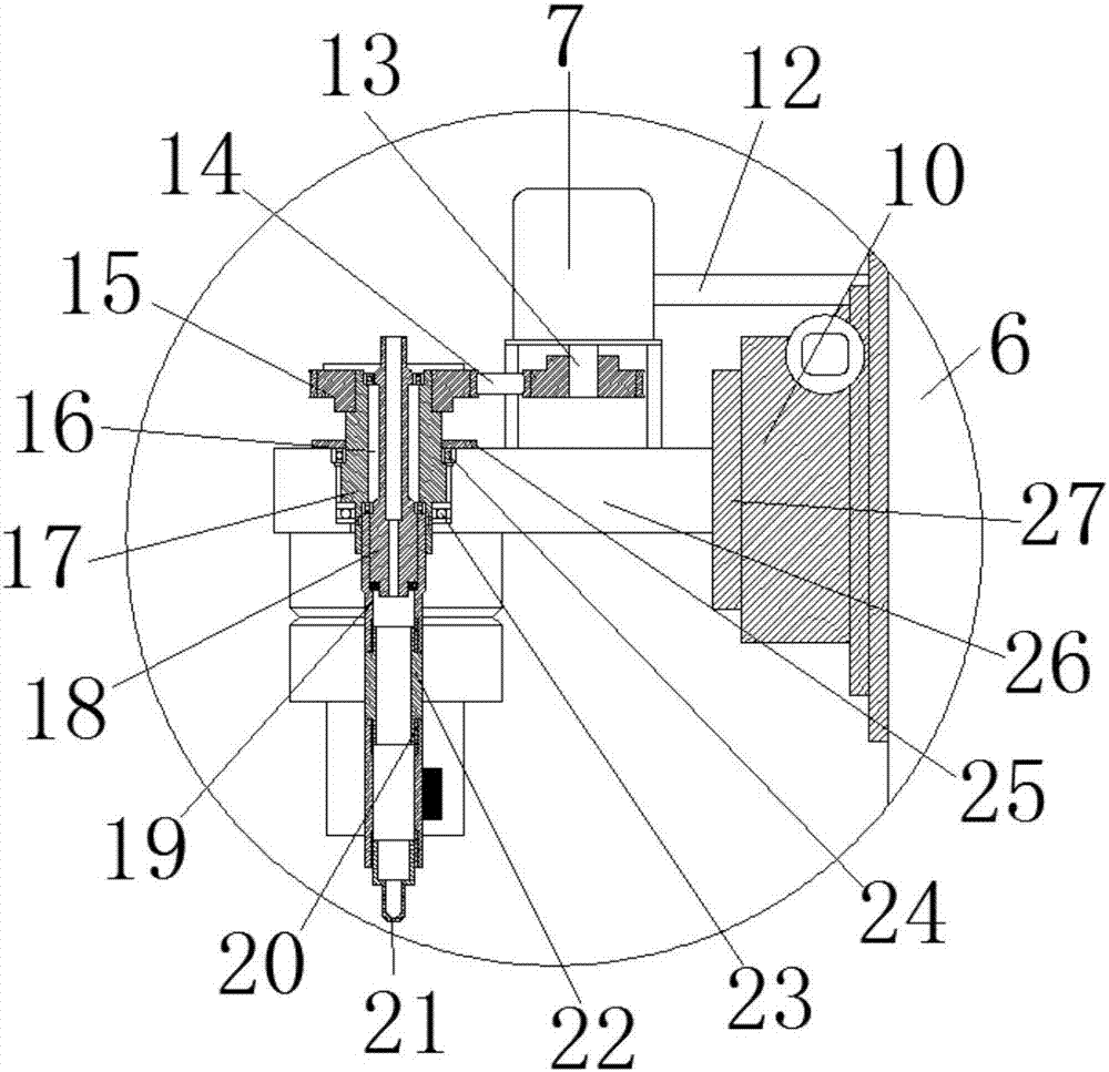
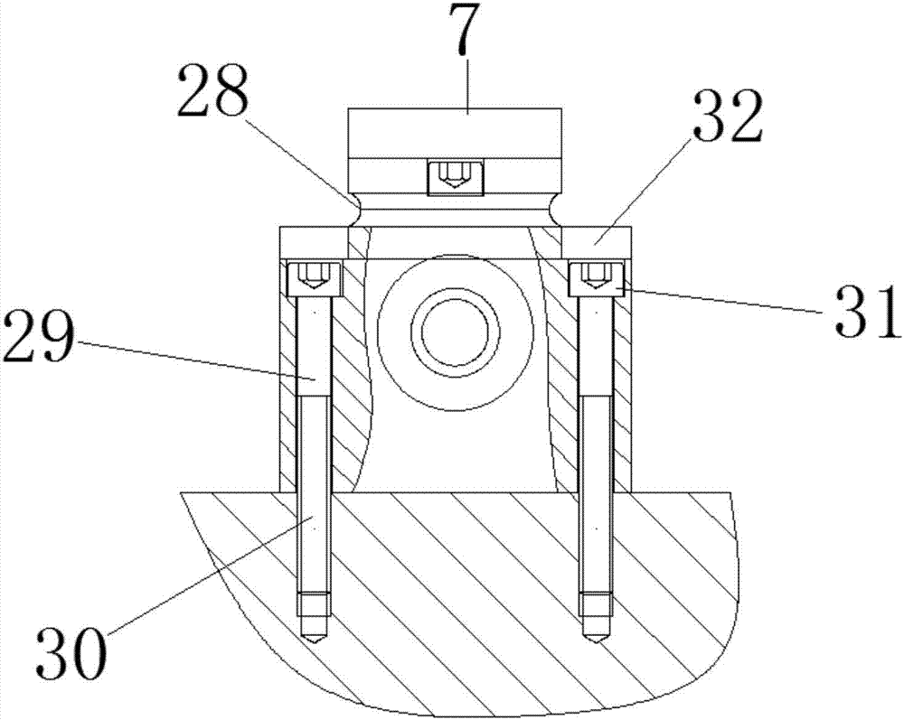
[0015] See Figure 1-3 , The present invention provides a technical solution: an electrochemical machining device, comprising a base 1, the base 1 is made of stainless steel, the lower surface of the base 1 is installed with a leg 2, the leg 2 is made of stainless steel, used to connect the base 1 More stable, the upper surface of the leg 2 is connected to the lower surface of the base 1. The inner wall of the base 1 is equipped with a s...


PUM


Abstract

The invention discloses an electrochemical machining device comprising a base. Supporting legs are installed on the lower surface of the base. The upper surfaces of the supporting legs are connected with the lower surface of the base. The inner wall of the base is provided with a lead screw. The outer wall of the lead screw is connected with the inner wall of the base. The outer wall of the lead screw is connected with a first nut seat in a sleeved manner. According to the electrochemical machining device, through the cooperation of the base, the supporting legs and the lead screw, under the action of the first nut seat, a machined piece can horizontally move on a workbench, the number of connection pipes can be increased through rotation, so that the machining distance can meet the requirement, and therefore the defect that the height of a fixed pipe of a traditional electrochemical machining device cannot be adjusted is overcome; and electrolyte can fall through the connection pipesand a dripping nozzle, blockage of the connection pipes, a fixed pipe and the dripping nozzle and the damage to the connection pipes are avoided, so that the defects that a traditional electrochemicalmachining device is not provided with an electrolyte guide pipe and connection pipes are prone to blockage or damage are overcome, and the overhauling cost is reduced for an enterprise.

Description

Technical field [0001] The invention relates to the technical field of mechanical processing, in particular to an electrolytic processing device. Background technique [0002] Traditional fine needle tip processing uses mechanical grinding, but the mechanically ground surface is relatively rough. For wire processing needle tips with a diameter of less than 0.5mm, the material loss is relatively large. Electrochemical machining is also called electrochemical machining (ECM) It is a processing method that uses the principle of electrochemical anode dissolution to remove materials. Electrochemical processing is due to the fast processing speed, high processing accuracy, good surface quality, no heat-affected layer, no macro cutting force, no loss of tool cathode, and no material strength, toughness, However, ordinary electrolysis or electric spark cannot control such a fine machining distance or produce such a fine cathode tip with a diameter of 0.5mm or less. In the prior art, for ...

Claims


Application Information

Patent Timeline
Patent Type & Authority Applications(China)
IPC IPC(8): B23H3/00B23H11/00B23Q1/26
CPCB23H3/00B23H11/003B23Q1/26
Inventor 梁荣强
Owner 青岛卫辽医用生物材料有限公司
Learn More