
Manual ultrasonic visual nondestructive detection device and method based on camera shooting positioning

A technology of non-destructive testing and detection devices, which is applied in the direction of measuring devices, processing detection response signals, and optical testing of flaws/defects. It can solve problems such as inability to detect on-site, large sensitivity loss, and inability to be portable, and achieve correction of color deviations in color codes. , Improve processing speed, and fast and accurate search effect

Inactive Publication Date: 2018-04-27
AEROSPACE RES INST OF MATERIAL & PROCESSING TECH +1
View PDF5 Cites 3 Cited by
  • Summary
  • Abstract
  • Description
  • Claims
  • Application Information

AI Technical Summary

Problems solved by technology

[0003] First of all, the automatic ultrasonic C-scan detection technology is more effective for flat or regular-shaped gyroscopic workpieces, but it is difficult to realize automatic detection for complex-shaped workpieces, or requires a large and complex system configuration
[0004] Secondly, the automatic ultrasonic C-scan detection technology has a large loss of sensitivity due to water coupling and other methods, and it is difficult to achieve high-sensitivity detection
[0005] Third, automatic ultrasonic C-scan detection technology is subject to the influence of system electrical noise, and the upper limit of detection sensitivity adjustment is limited
[0006] Fourth, automatic ultrasonic C-scan detection systems often have huge mechanical devices, cannot be portable, and cannot be tested on-site

Method used


Image

  • Manual ultrasonic visual nondestructive detection device and method based on camera shooting positioning
  • Manual ultrasonic visual nondestructive detection device and method based on camera shooting positioning
  • Manual ultrasonic visual nondestructive detection device and method based on camera shooting positioning

Examples


Embodiment Construction

[0047] Below in conjunction with accompanying drawing and specific embodiment the present invention is described in further detail:

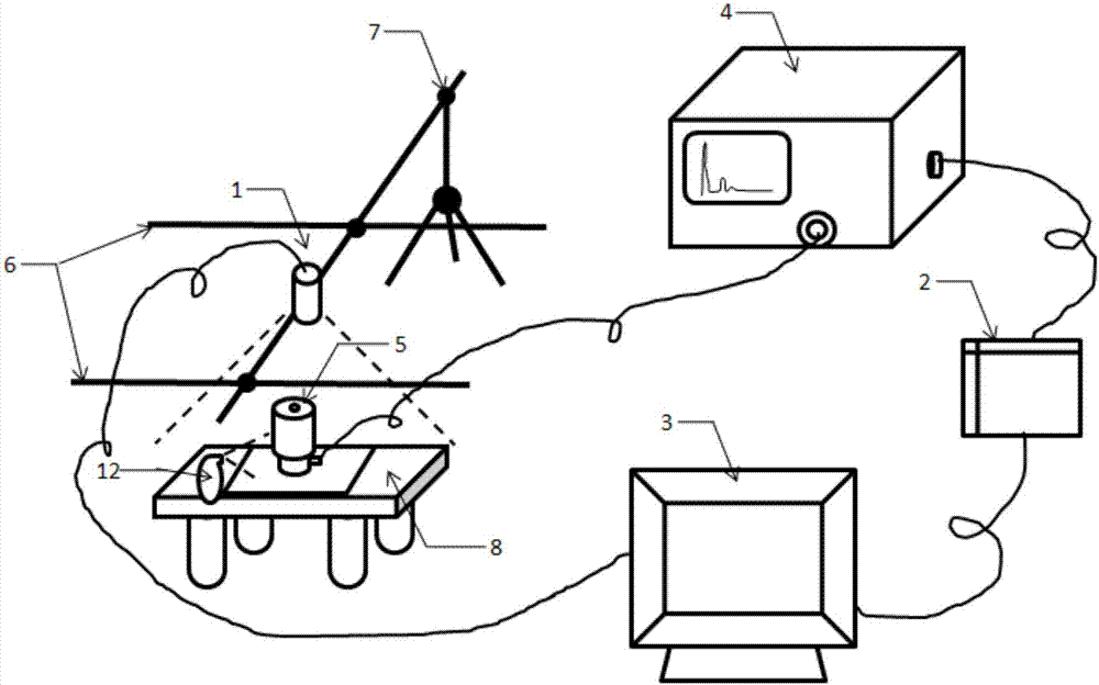
[0048] Such as figure 1 , 2 As shown, the present invention proposes an ultrasonic visualization nondestructive testing device based on camera positioning, including: camera 1, data acquisition card 2, industrial computer 3, ultrasonic flaw detector 4, detection device 5, stable light source 6, bracket 7 and working The stage 8 also includes a coupling device 12 for spraying a coupling agent on the surface of the object to be tested.

[0049] Camera 1: The full frame rate of the camera is required to be greater than 150 frames / s, the resolution greater than 1 million pixels, and the frame can be changed arbitrarily;

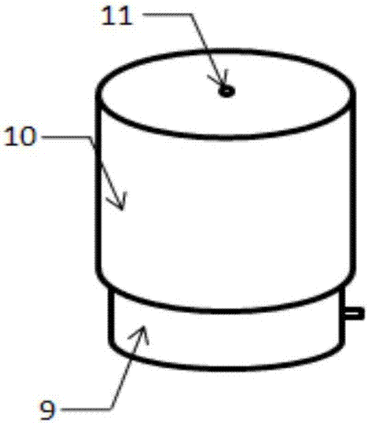
[0050] Ultrasonic flaw detector 4: generate electrical oscillation and apply it to the probe 9, excite the probe to generate ultrasonic waves, and after the ultrasonic waves propagate inside the inspected part, the probe receives...


PUM


Abstract

The invention relates to a manual ultrasonic visual nondestructive detection device and method based on camera shooting positioning. The device comprises a video camera, a data acquisition card, an industrial control computer, an ultrasonic flaw detector, a detector, stable light sources, a support and a workbench. The video camera and the stable light sources are both fixed on the support, the video camera is over against the workbench, the stable light sources are used for lighting the workbench, the detector is connected to the ultrasonic flaw detector, performs ultrasonic detection on a tested piece placed on the workbench, and provides the test data to the ultrasonic flaw detector, the data acquisition card collects the output data of the ultrasonic flaw detector and provides the datato the industrial control computer, the video camera provides the shot image data to the industrial control computer, and the industrial control computer processes the received image data and the output data of the ultrasonic flaw detector so as to obtain an ultrasonic C scanning detection image of the tested piece, thereby realizing ultrasonic visual nondestructive detection based on camera shooting positioning.

Description

technical field [0001] The invention relates to a manual ultrasonic visualization nondestructive testing device and method based on camera positioning, and belongs to the technical field of nondestructive testing. Background technique [0002] At present, the mature ultrasonic visual inspection technology includes automatic ultrasonic water immersion / water spray C-scan technology, but this technology still has some limitations: [0003] First of all, the automatic ultrasonic C-scan detection technology is more effective for flat or regular-shaped gyroscopic workpieces, but it is difficult to realize automatic detection for complex-shaped workpieces, or requires a large and complex system configuration. [0004] Secondly, the automatic ultrasonic C-scan detection technology has a large loss of sensitivity due to water coupling and other methods, and it is difficult to achieve high-sensitivity detection. [0005] Third, automatic ultrasonic C-scan detection technology is subj...

Claims


Application Information

Patent Timeline
Patent Type & Authority Applications(China)
IPC IPC(8): G01N29/44G01N21/88
CPCG01N21/8851G01N29/44G01N2291/023
Inventor 罗明何双起李丽陈颖张颖吴时红赵建华朱军辉
Owner AEROSPACE RES INST OF MATERIAL & PROCESSING TECH
Learn More