Electromagnetic dual-salient pole motor driving and charging integrated system of complex excitation winding
A technology of electric excitation double salient poles and excitation windings, which is applied in electric vehicle charging technology, motors, charging stations, etc., and can solve the problems of high cost and large land occupation
- Summary
- Abstract
- Description
- Claims
- Application Information
AI Technical Summary
Problems solved by technology
Method used
Image
Examples
Embodiment 1
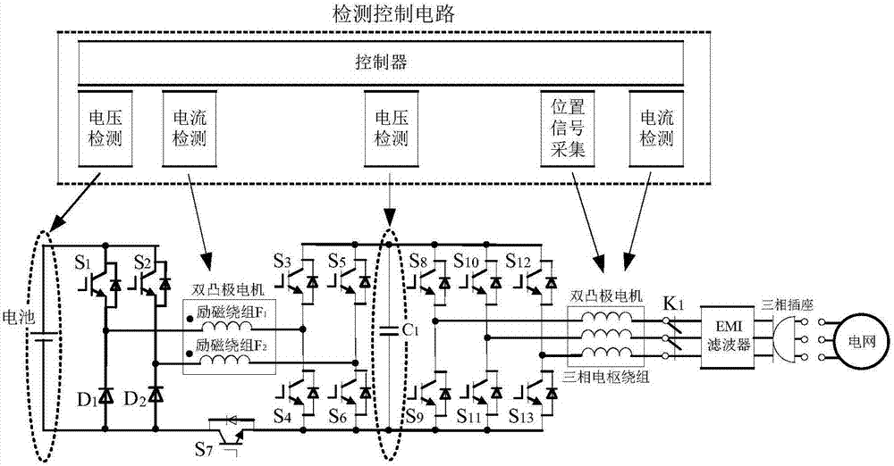
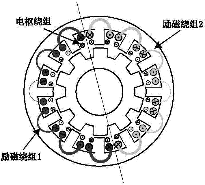
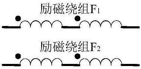
[0079] Such as figure 1 The driving and charging integrated system of the multiplexed excitation winding of the electrically excited double-salient pole motor shown in the figure, its vehicle-mounted part mainly includes a battery, a charge-discharge DC / DC converter, a three-phase bridge inverter, an electrically excited double-salient pole motor, Charge and discharge switch, EMI filter, charging socket, detection control circuit and controller (such as DSP28335, etc.), etc. Among them, the electric excitation double salient pole motor adopts a 12 / 10 pole structure, and the arrangement of its armature winding and two sections of excitation winding is as follows figure 2 As shown, when the number of excitation winding sections of the electrically excited doubly salient pole motor is greater than two sections, it can be divided into two sections in series or in parallel, as shown in image 3 Shown is a schematic diagram of four sections of excitation winding connected in serie...
Embodiment 2
[0082] In this example, on the basis of the first embodiment, the control strategy of the electric vehicle in the driving state is implemented.
[0083] 1) Toggle switch K 1 closed, the switch tube S 3 , S 5 , S 7 turn off;
[0084] 2) The battery voltage U is sampled by the voltage sensor bat , the excitation winding F is sampled by the current sensor 1 and field winding F 2 The excitation current I F1 and I F2 , I F1 and I F2 Ideally should be equal, let I F1 and I F2 equal to I F , switch tube S 1 and S 2 In the PWM state, the switch tube S is calculated according to the following relationship 1 , S 2 The duty cycle D 1 , ideally the switching tube S 1 and switch tube S 2 The duty cycle is equal, and the field winding F is controlled by this duty cycle 1 and field winding F 2 , so that the excitation current during steady-state operation is:
[0085]
[0086] T e is the given output torque of the motor, ω is the given speed of the motor, R F and R...
Embodiment 3
[0092]In this example, on the basis of the first embodiment, the control strategy of the electric vehicle in the braking state is implemented.
[0093] 1) Toggle switch K 1 closed, the switch tube S 7 turn on, the switch tube S 1 , S 2 , S 4 , S 6 turn off;
[0094] 2) The charging current of the battery and the current of the excitation winding obtained by the sampling of the current sensor, the switching tube S 3 , S 5 In the PWM state, control the battery charging current and the amplitude of the excitation winding current, that is, when the excitation winding current is too large, reduce the S 3 , S 5 duty cycle, when the excitation winding current is small, increase S 3 , S 5 duty cycle, and the battery charging current is the sum of the currents of the two excitation windings. At this time, the excitation winding current of the electrically excited double salient pole motor is in the reverse excitation state;
[0095] 3) At the same time, the position signal o...
PUM
 Abstract
Description
Claims
Application Information
 - R&D
- Intellectual Property
- Life Sciences
- Materials
- Tech Scout
- Unparalleled Data Quality
- Higher Quality Content
- 60% Fewer Hallucinations
Browse by: Latest US Patents, China's latest patents, Technical Efficacy Thesaurus, Application Domain, Technology Topic, Popular Technical Reports.
© 2025 PatSnap. All rights reserved.Legal|Privacy policy|Modern Slavery Act Transparency Statement|Sitemap|About US| Contact US: help@patsnap.com


