Supercharge Your Innovation With Domain-Expert AI Agents!

Full-automatic mechanical hand equipment

A robotic and fully automatic technology, applied in lighting and heating equipment, conveyors, conveyor objects, etc., can solve the problems of high labor costs, reduced product quality, slow processing efficiency, etc., to improve product consistency and ensure processing quality. , the effect of strong structural stability

Pending Publication Date: 2018-05-04
深圳市银浩自动化设备有限公司
View PDF0 Cites 3 Cited by
  • Summary
  • Abstract
  • Description
  • Claims
  • Application Information

AI Technical Summary

Problems solved by technology

[0003] First, the processing efficiency is slow and the degree of mechanization is low, which hinders industrial promotion and application;
[0004] Second, human error is prone to damage the glass or damage the carrier, and the glass may produce fingerprints and mold marks, which will reduce product quality;
[0005] The third is that the labor cost is high, which increases the production cost, and each piece of equipment needs to be equipped with skilled workers

Method used


Image

  • Full-automatic mechanical hand equipment
  • Full-automatic mechanical hand equipment
  • Full-automatic mechanical hand equipment

Examples


Embodiment Construction

[0035] The present invention will be further described below in conjunction with the accompanying drawings and specific embodiments. Terms such as "upper", "lower", "left", "right", "middle" and "one" quoted in the preferred embodiment are only for convenience of description, and are not used to limit the scope of the present invention. The scope of implementation and the change or adjustment of its relative relationship shall also be regarded as the scope of implementation of the present invention without substantive changes in technical content.

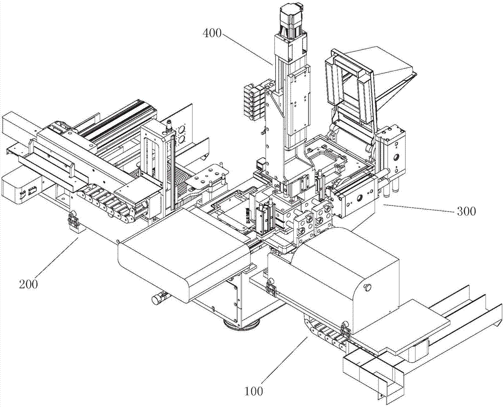
[0036] See figure 1 , a fully automatic manipulator device designed in a preferred embodiment of the present invention, which mainly includes: glass loading and placing mechanism 100, glass blanking and placing mechanism 200, carrier cleaning device 300 and loading and unloading arm 400, glass upper, The loading and unloading mechanism is symmetrically arranged on the left and right sides of the carrier cleaning device 300 , and t...


PUM


Abstract

The invention provides full-automatic mechanical hand equipment. The equipment comprises a glass feeding and placing mechanism, a glass discharging and placing mechanism, a carrier cleaning device anda feeding and discharging arm, wherein the glass feeding and placing mechanism is used for placing glass to be machined from a raw material frame to a feeding carrying table, the glass discharging and placing mechanism is used for placing formed glass from a discharging carrying table to a finished product frame, and the feeding and discharging arm moves back and forth among the glass feeding andplacing mechanism, the glass discharging and placing mechanism and the carrier cleaning device. The carrier cleaning device comprises a cabinet, an upper carrier cleaning station, a lower carrier cleaning station, a lower carrier turnover assembly and a gas circulating system, wherein the upper carrier cleaning station and the lower carrier cleaning station are arranged at the upper end of the cabinet side by side in a front and back manner, the lower carrier turnover assembly drives the lower carrier cleaning station to be turned over downwards, and the gas circulating system is used for cleaning the inner surface of an upper cover and the inner surface of a lower cover. The glass feeding and placing mechanism and the glass discharging and placing mechanism are arranged on the left sideand the right side of the cabinet oppositely and correspondingly. The feeding and discharging arm comprises an arm frame, an upper carrier clamping assembly, a lower carrier clamping assembly and a glass moving and carrying assembly, wherein the upper carrier clamping assembly, the lower carrier clamping assembly and the glass moving and carrying assembly are installed at the bottom end of the armframe. The full-automatic feeding and discharging mechanical arm equipment is designed and developed, feeding and discharging of a hot bending machine are operated in a full mechanical automation manner, and the working efficiency is improved.

Description

technical field [0001] The invention relates to a loading and unloading manipulator used in conjunction with various mechanical equipment, and more particularly relates to a fully automatic loading and unloading manipulator used for a 3D glass hot bending machine. Background technique [0002] During the processing of the hot bending machine, it is necessary to use a loading and unloading manipulator. The loading and unloading manipulator sends the carrier containing the glass to be processed into the hot bending machine. After the hot bending process is completed, the loading and unloading manipulator takes out the carrier and then opens the carrier. Cut the formed glass. At present, the loading and unloading process of the hot bending machine is mostly completed by various auxiliary manipulators + manual use of various fixtures. The problems of this operation are: [0003] First, the processing efficiency is slow and the degree of mechanization is low, which hinders indus...

Claims


Application Information

Patent Timeline
IPC IPC(8): B65G49/06
CPCB65G49/067B65G2249/04
Inventor 王洪文
Owner 深圳市银浩自动化设备有限公司
Features
  • R&D
  • Intellectual Property
  • Life Sciences
  • Materials
  • Tech Scout
  • Unparalleled Data Quality
  • Higher Quality Content
  • 60% Fewer Hallucinations
Learn More