
Corn lamp made of SMD lamp beads and conductive lines bent

A technology of conductive lines and corn lamps, which is applied in the direction of circuit layout, components of lighting devices, semiconductor devices of light-emitting elements, etc., can solve the problems that affect the popularization and use, and the cost of the whole lamp remains high, so as to reduce the production process and production Cost, precise assembly process, and the effect of ensuring product quality

Active Publication Date: 2019-09-03
邓放明
View PDF9 Cites 1 Cited by
  • Summary
  • Abstract
  • Description
  • Claims
  • Application Information

AI Technical Summary

Problems solved by technology

[0002] Since LEDs have been used for lighting, the forms of lighting fixtures have become more diverse. For those lamps that are not convenient to install radiators, they usually use the attachment of aluminum substrates, glass fiber boards or flexible boards for natural heat dissipation. For this natural Heat-dissipating LED lamps usually use large-area chip lamp beads or a large number of lamp beads to reduce the junction temperature as much as possible. For this type of LED lamps, the heat dissipation area of ​​aluminum substrate or glass fiber board is usually relatively large, so as to meet the requirements of LED lamps. In normal use, during the production process of corn-shaped LED energy-saving lamps, due to the large area of ​​the aluminum substrate and the large number of lamp beads of this lamp, the cost of the whole lamp remains high, which affects the popularization and use

Method used


Image

  • Corn lamp made of SMD lamp beads and conductive lines bent
  • Corn lamp made of SMD lamp beads and conductive lines bent
  • Corn lamp made of SMD lamp beads and conductive lines bent

Examples


Embodiment

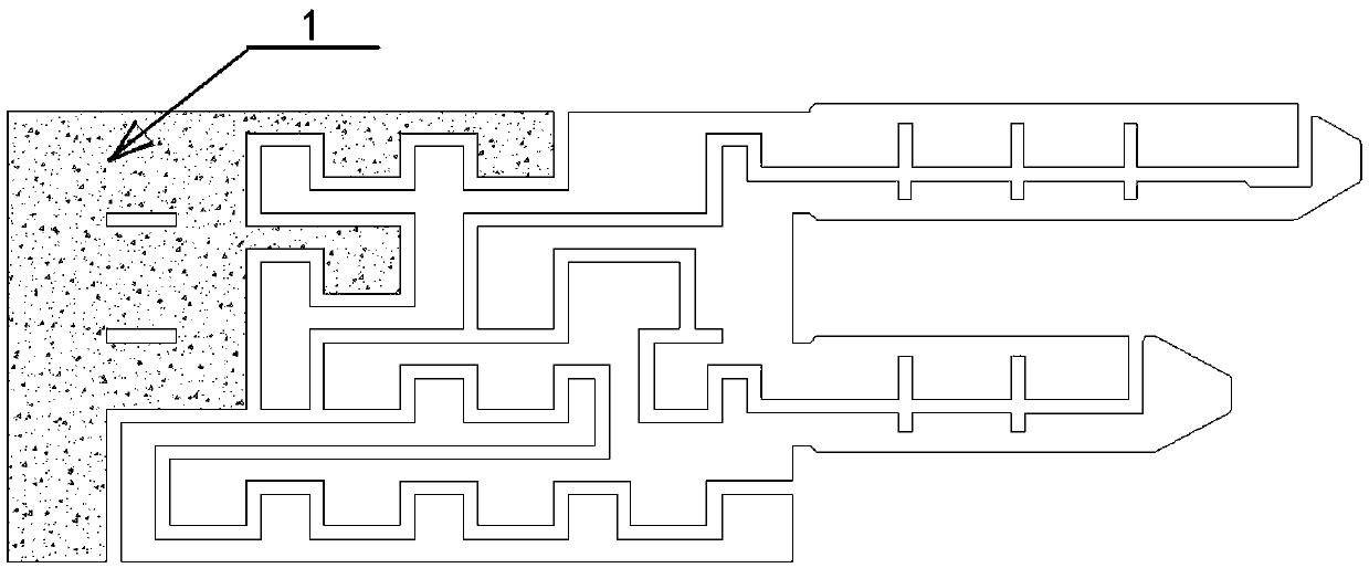
[0052] Choose a flat tinplate sheet with a thickness of 0.2, with a length and width of 170X85, and paint the solder mask oil 22 (solder mask screen) on the circuit diagram with white oil, such as Figure 16 , a circular pad 17 and a lamp bead pad 18 are arranged on it;

[0053] In the figure, the three circular pads in the lower left corner, lower right corner, and upper right corner are the positioning holes 19 of the punching machine. The positioning holes are drilled with a drill press, and the first punching is performed. After punching, the positioning ribs and bends are left on the board. Auxiliary tendons, such as Figure 17 ;

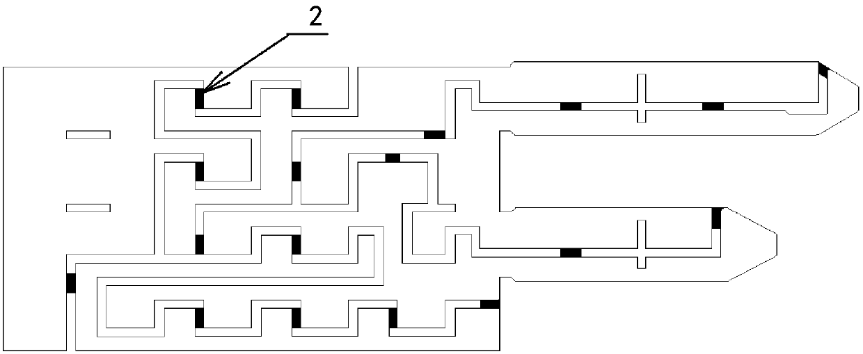
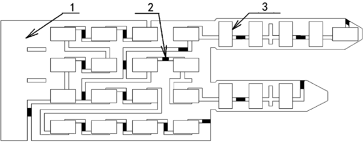
[0054] Brush the solder paste on the board that was punched out for the first time, paste the patch lamp beads (5630 lamp beads), go through reflow soldering, and then paste the insulating positioning block on the line isolator, such as Figure 18 ;

[0055] Perform the second punching, remove the positioning ribs, and retain the bending aux...


PUM


Abstract

The invention discloses a patch lamp bead and electric conducting circuit bent corn lamp. The patch lamp bead and electric conducting circuit bent corn lamp is manufactured by the method steps of (a)mold pretreatment, (b) secondary punching, (c) bending: the one-standing and one-moving bending is performed; one standing: a static cutting board is arranged on one side of a rotary bending axis; a row of lamp beads and electric conducting metal among the lamp beads are pressed on the cutting board; and pressing pieces are pressing bars continuously spaced and with the heights of the lamp beads as step heights and bonded with rubber pad layers on the contacted surfaces; and one moving: a rotary bending plate is arranged on the other side of the rotary bending axis, and performs a rotary bending motion with the rotary bending axis as shaft; (d) assembly and light source molding, and (e) inner and outer insulation. An attachment heat dissipating plate of an aluminum substrate or a glass fiber plate or a flexible plate is saved, so that the production process and the production cost are greatly reduced; the process difficulty of mold opening through LED energy saving lamp punching and the like is reduced, so that later procedures of the production process are guaranteed; and the LED energy saving lamp bending and assembly processes are more precise to guarantee the product quality.

Description

technical field [0001] The invention relates to the technical field related to the manufacture of energy-saving lamps, in particular to an LED energy-saving lamp in which chip lamp beads are mounted on a metal conductive circuit and the conductive circuit is bent into a corn shape. Background technique [0002] Since LEDs have been used for lighting, the forms of lighting fixtures have become more diverse. For those lamps that are not convenient to install radiators, they usually use the attachment of aluminum substrates, glass fiber boards or flexible boards for natural heat dissipation. For this natural Heat-dissipating LED lamps usually use large-area chip lamp beads or a large number of lamp beads to reduce the junction temperature as much as possible. For this type of LED lamps, the heat dissipation area of ​​aluminum substrate or glass fiber board is usually relatively large, so as to meet the requirements of LED lamps. In normal use, during the production process of c...

Claims


Application Information

Patent Timeline
Patent Type & Authority Patents(China)
IPC IPC(8): F21K9/90F21V23/00F21Y107/30F21Y115/10
Inventor 邓放明
Owner 邓放明
Learn More