Triple-frequency micro-strip slot antenna

A technology of microstrip slots and microstrip lines, which is applied in the direction of slot antennas, antennas, and devices that enable antennas to work in different bands at the same time, can solve the problems of low data transmission efficiency, achieve high reproducibility, simple adjustment methods, good practical effect

Inactive Publication Date: 2018-05-04
台州市吉吉知识产权运营有限公司
View PDF2 Cites 3 Cited by
  • Summary
  • Abstract
  • Description
  • Claims
  • Application Information

AI Technical Summary

Problems solved by technology

The antenna structure can be realized directly on the motherboard by metal etching, without any other components, and without reserving the antenna clearance area; using double C-shaped slots, the WIFI dual-band work is realized, and the space occupied is small, but only dual-band work can be achieved. Data transfer efficiency is relatively low

Method used


Image

  • Triple-frequency micro-strip slot antenna
  • Triple-frequency micro-strip slot antenna
  • Triple-frequency micro-strip slot antenna

Examples


Embodiment 1

[0034] Such as figure 1 As shown, this embodiment provides a three-band microstrip slot antenna, including a dielectric board 1 and a ground plane 2 arranged front and back, wherein the ground plane 2 has a complete grounding arrangement, and the dielectric board 1 is provided with a microstrip line 11, The ground plate 2 is provided with a gap 21 at the microstrip line 11 corresponding to the dielectric plate 1; in detail, the dielectric plate 1 and the ground plate 2 have the same shape and size, and the positions are arranged front and back. The dielectric plate 1 can be It is equivalent to the TOP layer of the PCB board that has been cleaned, and the ground plane 2 can be equivalent to the BOTTOM layer of the PCB board in nature. Therefore, in this embodiment, the microstrip line 11 and the ground plane 2 are arranged The gaps 21 can be set on the PCB board through the production process, so as to save the space occupied when the antenna is set;

[0035] The microstrip li...

Embodiment 2

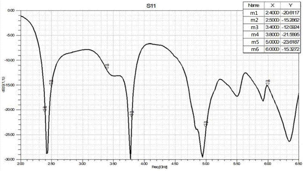
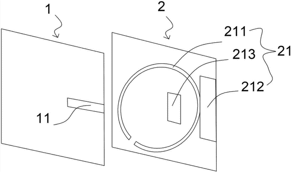
[0040] The difference between this embodiment and Embodiment 1 is that this embodiment summarizes the detailed positional relationship among the non-closed annular groove 211, the radiation groove 212 and the adjustment groove 213 based on the results of multiple simulations, which can produce better radiation characteristics. ,Such as figure 2As shown, the radiation groove 212 is arranged on the outside of the non-closed annular groove 211 and the two are in contact with each other. Specifically, the radiation groove 212 and the non-closed annular groove 211 are sequentially arranged upward from the lower bottom edge of the ground plate 2. The radiation groove The long side of 212 is arranged parallel to the lower bottom side of the ground plate 2. Under the position distribution of the above-mentioned radiation slot 212 and the non-closed annular slot 211, the signal transmission has a relatively high impedance bandwidth, and the radiation characteristics and frequency cover...

Embodiment 3

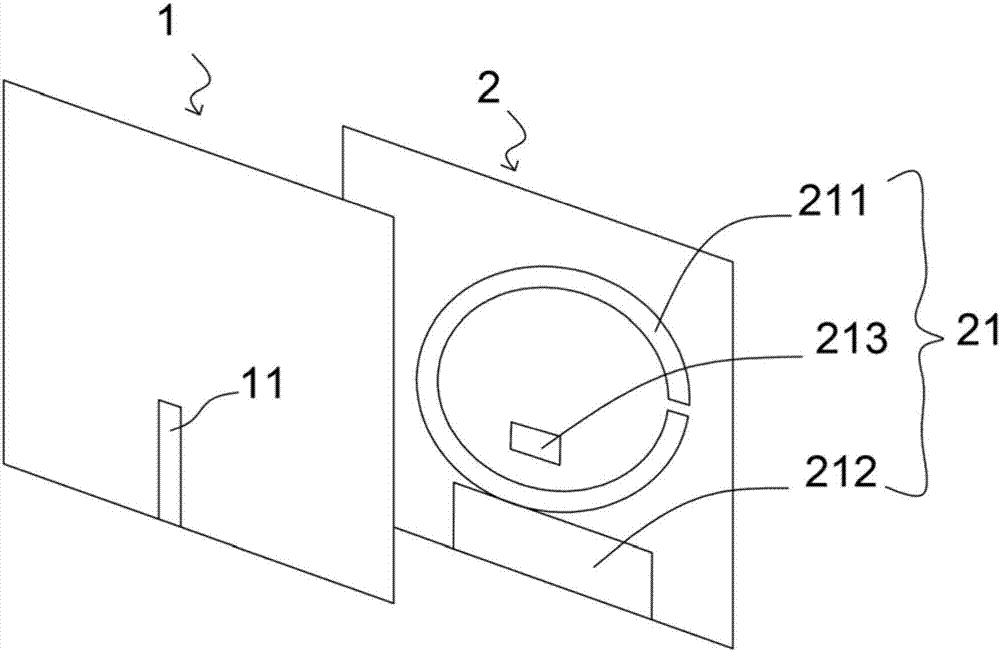
[0049] Such as image 3 As shown, the difference between this embodiment and Embodiment 2 is that the adjustment groove 213 is a U-shaped groove, and the opening direction of the adjustment groove 213 is consistent with the opening direction of the non-closed annular groove 211, so as to ensure better Feed coupling to reduce electromagnetic radiation interference signal. The width of the adjustment groove 213 and the non-closed annular groove 211 can be the same or different, and the widths of different sides of the adjustment groove 213 can also be the same or different, usually the width of each side of the adjustment groove 213 and the distance between the adjustment groove 213 and the non-closed annular groove 211 The distance between them can be adjusted according to impedance matching, working frequency band and wireless communication standard, that is, the working frequency of the antenna can be changed by adjusting the length and / or width of the slot 213 .

[0050] In...


PUM


Abstract

The invention discloses a Triple-frequency micro-strip slot antenna. The Triple-frequency micro-strip slot antenna comprises a front dielectric plate and a rear grounding plate and is characterized inthat the dielectric plate is provided with a micro-strip line, a position, corresponding to the micro-strip of the dielectric plate, of the grounding plate is provided with a slot, and the slot comprises a non-closed annular groove, a radiation groove and a regulation groove. The Triple-frequency micro-strip slot antenna has the advantages that an extra plug-in does not need to be added, a coupling feeding mode is used, excellent-performance Triple-frequency work can be achieved, and the Triple-frequency micro-strip slot antenna is easy in integration, easy in machining, small in size, smallin space occupation, good in radiation performance and low in production cost.

Description

technical field [0001] The invention relates to the technical field of antennas, in particular to a triple-frequency microstrip slot antenna. Background technique [0002] With the rapid development of wireless communication technology, the application of antennas is becoming more and more extensive, and the performance requirements of antennas are also getting higher and higher. With the development of miniaturization of wireless communication products, antennas are indispensable for transmitting and receiving radio frequency signals in wireless communication. In addition to the requirements for performance to support more frequency bands, the components have more and more stringent requirements on size, weight and volume. [0003] Currently, WIFI based on the 802.11n standard has two operating frequency bands, 2.4GHz and 5.8GHz. Most countries use the 2.4GHz frequency band more often. WiMAX based on 802.16 can provide higher-speed broadband in a wider geographical range th...

Claims


Application Information

Patent Timeline
Patent Type & Authority Applications(China)
IPC IPC(8): H01Q1/38H01Q13/10H01Q5/28H01Q5/307
CPCH01Q1/38H01Q5/28H01Q5/307H01Q13/106
Inventor 陈西杰
Owner 台州市吉吉知识产权运营有限公司
Why Eureka
Try Eureka