
Eye imaging system, method and device

An imaging system and eye technology, applied in the field of imaging systems, can solve problems such as difficulty in portability, uneven illumination, bulky volume, etc., and achieve the effect of improving the possibility

Active Publication Date: 2020-06-26
SHANGHAI MEDIWORKS PRECISION INSTR CO LTD
View PDF4 Cites 0 Cited by
  • Summary
  • Abstract
  • Description
  • Claims
  • Application Information

AI Technical Summary

Problems solved by technology

Traditional eye imaging systems are bulky, difficult to carry, expensive and unpopular, cumbersome to operate, and difficult to apply to bedridden patients. They are gradually replaced by hand-held eye imaging systems. The design is simple, and there are imaging problems such as uneven illumination, inaccurate working distance, and defocusing caused by chromatic aberration, especially the inaccurate working distance. During operation, the image is often formed at the front and rear of the working distance, and the resolution of the obtained eye image cannot reach the best. Excellent effect; there is also the elimination of chromatic aberration. The current solution is generally to use an achromatic lens in the optical design, which reduces the influence of chromatic aberration on imaging to a certain extent, but it is still impossible to achieve infrared and white light. High-definition imaging at the same working position

Method used


Image

  • Eye imaging system, method and device
  • Eye imaging system, method and device
  • Eye imaging system, method and device

Examples


Embodiment Construction

[0063] The present invention will be described in detail below in conjunction with specific embodiments. The following examples will help those skilled in the art to further understand the present invention, but do not limit the present invention in any form. It should be noted that those skilled in the art can make several changes and improvements without departing from the concept of the present invention. These all belong to the protection scope of the present invention.

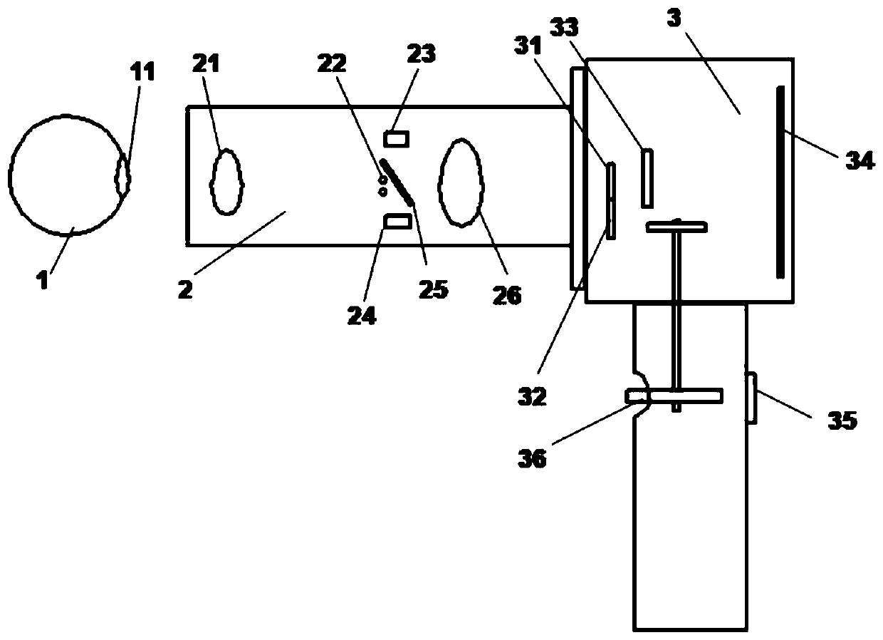
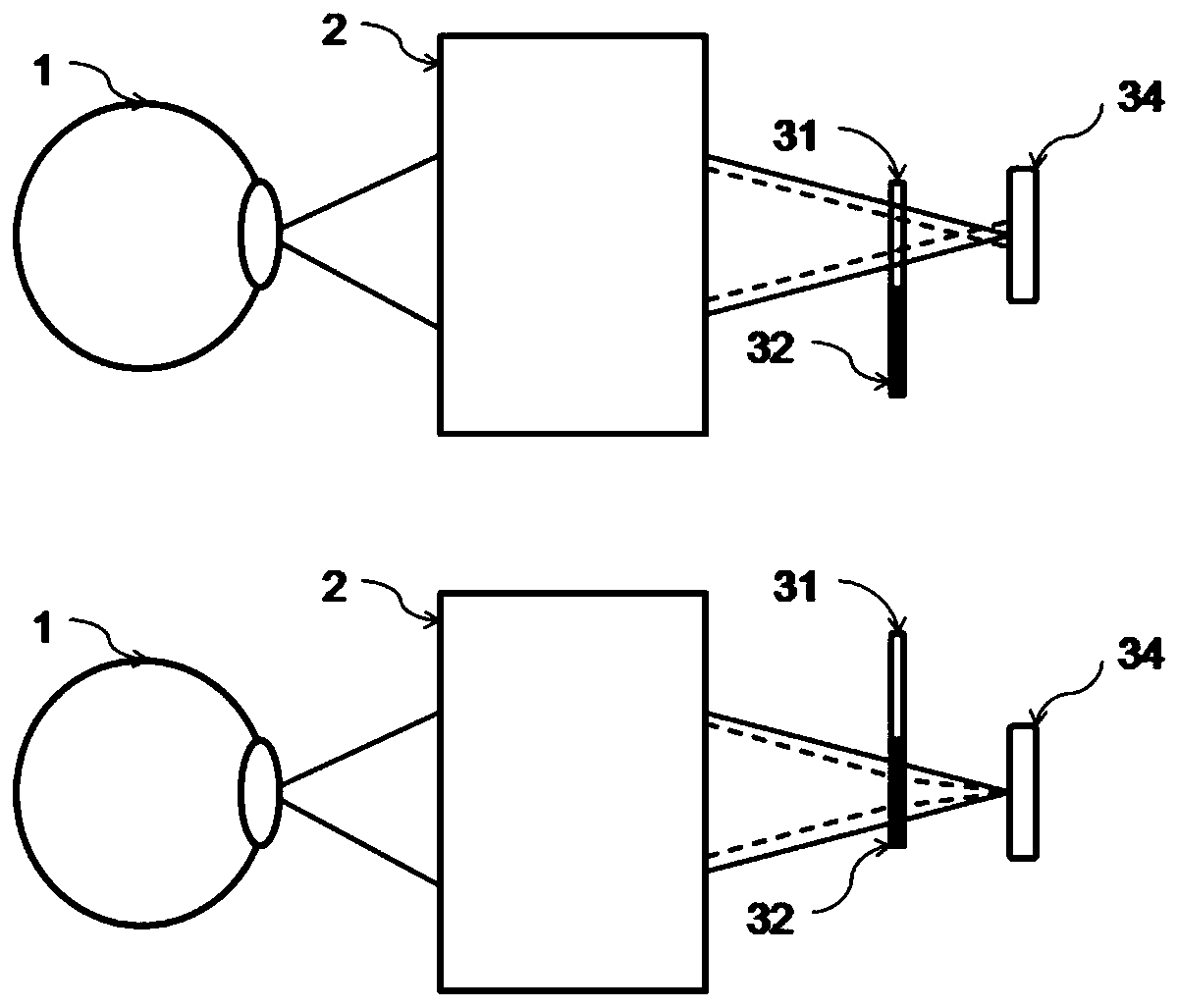
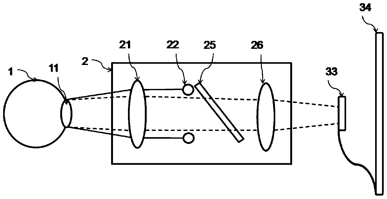
[0064] An eye imaging system provided according to the present invention includes an optical path control module, a light source module, a photosensitive module 33 and a display module 34; the eye imaging system includes a plurality of optical paths; one optical path is for the light source module to generate light passing through The optical path control module shoots to the eye 1, and the light reflected from the eye 1 is projected to the photosensitive module 33 through the optical path control module...


PUM


Abstract

An eye imaging system comprises an optical path control module, a light source module, a light sensing module (33), and a display module (34). The eye imaging system comprises multiple optical paths. One optical path is a path of a light ray generated by the light source module passing through the optical path control module and then proceeding to an eye (1). A returning light ray (1) reflected by the eye (1) passes through the optical path control module and then projects to the light sensing module (33) to be displayed on the display module (34). The eye imaging system achieves high-resolution imaging of a fundus lesion. The eye imaging system incorporates a technique of pupil positioning, and uses an LED light source to illuminate a pupil (11) of an eye to and acquires reflected light from the pupil (11) to determine an accurate operation distance.

Description

technical field [0001] The present invention relates to an imaging system, in particular to an eye imaging system, method and device. Background technique [0002] With the continuous advancement and development of science and technology, people pay more attention to the primary screening of eye diseases, especially the screening of fundus diseases such as diabetic retinopathy. Traditional eye imaging systems are bulky, difficult to carry, expensive and unpopular, cumbersome to operate, and difficult to apply to bedridden patients. They are gradually replaced by hand-held eye imaging systems. The design is simple, and there are imaging problems such as uneven illumination, inaccurate working distance, and defocus caused by chromatic aberration, especially the inaccurate working distance. During operation, images are often formed at the front and rear of the working distance, and the resolution of the obtained eye image cannot reach the best. Excellent effect; there is also ...

Claims


Application Information

Patent Timeline
Patent Type & Authority Patents(China)
IPC IPC(8): A61B3/12A61B3/14
CPCA61B3/12A61B3/14
Inventor 张锐进黄晓燕陈文光
Owner SHANGHAI MEDIWORKS PRECISION INSTR CO LTD
Learn More