Nitrogen tetroxide leakage collection device and method

A dinitrogen tetroxide and collection equipment technology, applied in the field of dinitrogen tetroxide leakage collection, can solve the problems of poor environmental protection, limited availability of dinitrogen tetroxide, low safety performance, etc.

Inactive Publication Date: 2018-05-08
BEIJING INST OF AEROSPACE TESTING TECH +1
View PDF5 Cites 10 Cited by
  • Summary
  • Abstract
  • Description
  • Claims
  • Application Information

AI Technical Summary

Problems solved by technology

[0002] Dinitrogen tetroxide can spontaneously ignite with many fuels, and is an excellent oxidant, widely used in rocket propellants, the molecular formula is N 2 o 4 , a colorless gas, a strong oxidant, with a boiling point of 21.5°C, it is a liquid at this temperature, but its liquid temperature range is very narrow, and it is easy to freeze and evaporate
[0004] But this invention has the following disadvantages. First, the recycling system is not provided with a filter device, and the reacted nitrogen dioxide is directly discharged into the atmosphere, and a small part of unreacted nitrogen tetroxide gas will also be discharged with the reaction process. Nitrogen dioxide is directly discharged, which is poor in environmental protection; secondly, because nitrogen tetroxide reacts with water and air, a certain pressure needs to be ensured, so when there is a problem with the pressure device, it is easy to cause the collapse of the entire recovery system, and even a large amount of tetraoxide Dinitrogen is discharged into the atmosphere without reaction, and the safety performance is low; in addition, the recovery system limits the availability of recovered dinitrogen tetroxide, which can only be reused as dilute nitric acid, which is not conducive to saving resources

Method used


Image

  • Nitrogen tetroxide leakage collection device and method
  • Nitrogen tetroxide leakage collection device and method
  • Nitrogen tetroxide leakage collection device and method

Examples


Embodiment 1

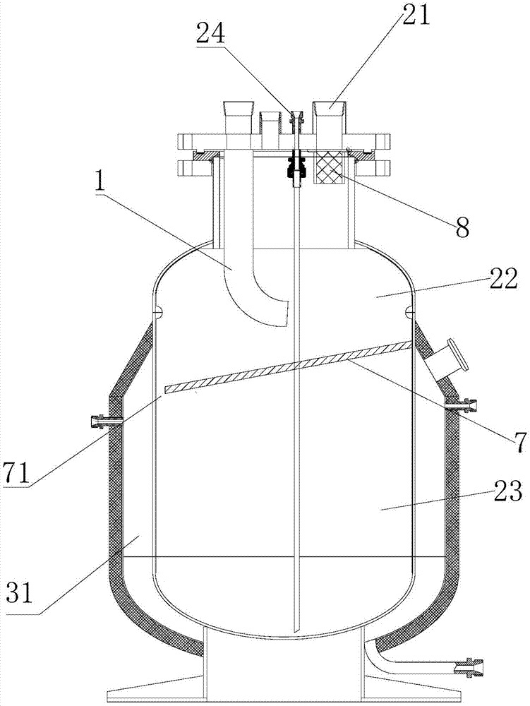
[0036] like figure 2 As shown, the chamber inner wall of the collection container 2 is equipped with a partition plate 7, and the partition plate 7 divides the collection container 2 into an upper gas-liquid separation area 22 and a lower liquid collection area 23, and the separation plate 7 is provided with at least A through hole 71 communicating the gas-liquid separation zone 22 with the lower liquid collection zone 23 . The gas-liquid mixture stays on the partition plate 7 for a period of time to fully condense, so as to prevent the mixed liquid from entering the lower part of the collection container 2 without sufficient gas-liquid separation. In order to facilitate the flow of liquid into the liquid collection area, the partition plate 7 has a downwardly inclined angle of 10°-30°, and a through hole 71 is provided at the lowest point.

[0037] like image 3 As shown, as a further preferred mode of the embodiment of the present invention, the absorption device 6 is at ...

Embodiment 2

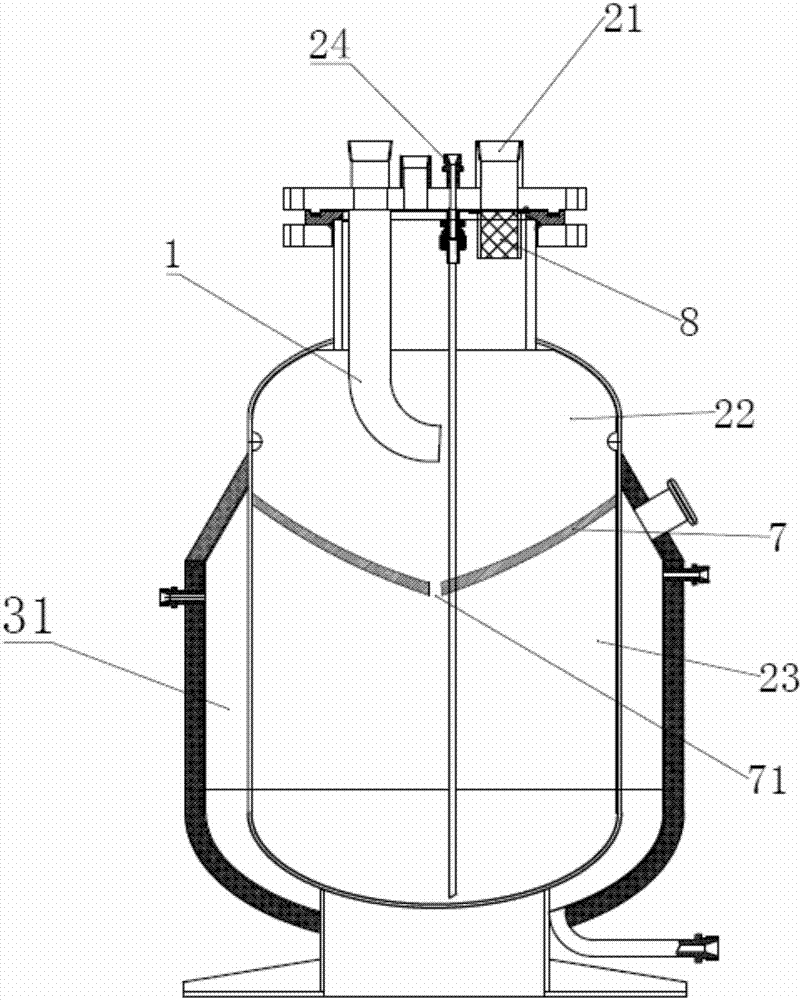
[0044] like image 3 As shown, the difference between this embodiment and the above-mentioned embodiment lies in the design of the partition plate 7, the chamber inner wall of the collection container 2 is equipped with a partition plate 7, and the partition plate 7 separates the collection container 2 into the upper gas-liquid separation. Between the zone 22 and the lower liquid collection zone 23 , the partition plate 7 is funnel-shaped with its apex downward, and the partition plate 7 is provided with at least one through hole 71 communicating the gas-liquid separation zone 22 and the lower liquid collection zone 23 . Preferably, the through hole 71 is arranged at the lowest level of the partition plate 7 . When the leakage liquid enters the collection container 2 through the collection pipe 1, it flows to the partition plate 7 under the action of gravity. Since the partition plate 7 is shaped like a funnel with the apex downward, when the mixed liquid enters the collection...

Embodiment 3

[0047] The only difference between this embodiment and the above embodiment is that the vortex air pump is replaced by a vacuum pump, and the vacuum pump is used to suck dinitrogen tetroxide waste liquid and waste gas.

[0048] Describe below in conjunction with the specific work process of the present invention:

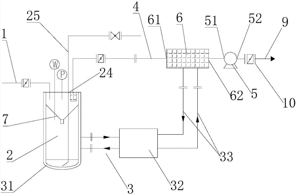
[0049] like figure 1 As shown, when it is necessary to collect the leakage liquid, open the control switch of the equipment and the valves of each pipeline, and use the negative pressure absorption device 5 as the driving force to suck the leakage liquid / gas into the collection container 2 through the collection pipeline 1 for gas-liquid separation In the zone 22, the gas-liquid mixture is condensed by the cooling system 3 to reduce the evaporation of the liquid, and since the collecting container 2 is provided with a partition plate 7, the partition plate 7 is shaped like a funnel with the apex downward. When the direction enters the collection container 2, the li...


PUM


Abstract

The invention discloses a nitrogen tetroxide leakage collection device and method. The nitrogen tetroxide leakage collection device comprises a collection pipe, a collection container connected to thecollection pipe, an exhaust gas treatment module, a high negative pressure suction device and an electronic control module. The collection container and the exhaust gas treatment module are providedwith cooling systems. The upper part of the collection container is provided with a gas outlet. The gas outlet is connected to the negative pressure suction device through a gas suction pipe. The gassuction pipe between the collection container and the negative pressure suction device is provided with an absorption device for removing exhaust gas. Through being driven by the negative pressure suction device, the leaked nitrogen tetroxide liquid/gas and nitrogen dioxide are sucked into the inner collection container through the collection pipe, the gas-liquid mixture is subjected to gas-liquidseparation and cooling liquidation, the nitrogen tetroxide liquid is collected, and the tail gas is subjected to adsorption filtration so that toxic and hazardous substances in the tail gas are removed and thus collection efficiency is high and the environmental protection and conservation of resources are realized.

Description

technical field [0001] The invention relates to the technical field of chemical industry, in particular to a device for collecting dinitrogen tetroxide leaks during work, and a method for collecting dinitrogen tetroxide leaks using the device. Background technique [0002] Dinitrogen tetroxide can spontaneously ignite with many fuels, and is an excellent oxidant, widely used in rocket propellants, the molecular formula is N 2 o 4 , a colorless gas, a strong oxidant, with a boiling point of 21.5°C, it is a liquid at this temperature, but its liquid temperature range is very narrow, and it is easy to solidify and evaporate. Dinitrogen tetroxide at room temperature is in a state of continuous vaporization. Dinitrogen tetroxide suspended in the air immediately decomposes into nitrogen dioxide gas under reduced pressure. Nitrogen dioxide gas is brownish red and has neuronarcotic toxicity. At present, dinitrogen tetroxide leaks from time to time during production and work. Din...

Claims


Application Information

Patent Timeline
Patent Type & Authority Applications(China)
IPC IPC(8): B01D53/00B01D53/14B01D53/02B01D45/16B01D45/08B01D46/00C01B21/36
CPCB01D45/08B01D45/16B01D46/00B01D53/002B01D53/02B01D53/14B01D53/1406B01D2257/404C01B21/36Y02C20/10
Inventor 郑雪玲孙鹤荆彦文郝战焱闫子良郭振刘岩金朝旭郝龙徐光刘朝阳许宏
Owner BEIJING INST OF AEROSPACE TESTING TECH
Why Eureka
Try Eureka