

Method for cladding steel rail with alloy without cooling rate control
A cladding alloy and speed control technology, which is applied in the field of rail cladding, can solve problems such as limited use, low temperature in winter, and slow construction speed, so as to improve corrosion resistance and wear resistance, and improve wear resistance and corrosion resistance performance, protection of wear resistance and corrosion resistance
- Summary
- Abstract
- Description
- Claims
- Application Information
AI Technical Summary
Problems solved by technology
Method used
Image

Examples
Embodiment 1
[0058] A steel rail cladding alloy method without cooling rate control, comprising the following steps:
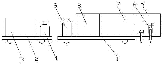
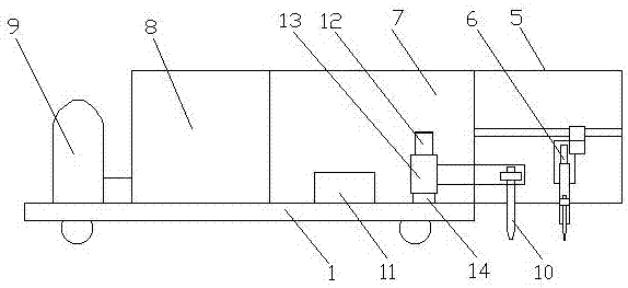
[0059] a. Place the rail cladding machine on the rail, the plasma welding torch 10 on the rail cladding machine moves at a constant speed with the first mobile trolley 1, and the plasma welding torch 10 cladding alloy above the rail head tread surface to be clad;
[0060] b. The alloy strip formed after alloy cladding is located on the inner side of the center of the rail head tread, the width of the alloy strip is 4mm, and the thickness of the heat-affected zone of the rail is controlled at 0.3mm;
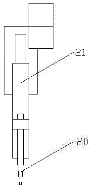
[0061]c. Arrange the flame head 20 on the rail cladding machine above the alloy strip after cladding; use the mixed gas formed by liquefied gas and oxygen as the heating gas source, and mix the liquefied gas and oxygen directly on the flame head 20; cladding After the final alloy strip is left to stand for 2 seconds, start to move the flame head 20 at a constant speed along th...
Embodiment 2
[0065] A steel rail cladding alloy method without cooling rate control, comprising the following steps:
[0066] a. Place the rail cladding machine on the rail, the plasma welding torch 10 on the rail cladding machine moves at a constant speed with the first mobile trolley 1, and the plasma welding torch 10 cladding alloy above the rail head tread surface to be clad;
[0067] b. The alloy strip formed after alloy cladding is located on the inner side of the center of the rail head tread, the width of the alloy strip is 10mm, and the thickness of the heat-affected zone of the rail is controlled at 1mm;
[0068] c. Arrange the flame head 20 on the rail cladding machine above the alloy strip after cladding; use the mixed gas formed by liquefied gas and oxygen as the heating gas source, and mix the liquefied gas and oxygen directly on the flame head 20; cladding After the final alloy strip is left to stand for 20 seconds, start to move the flame head 20 at a constant speed along t...
Embodiment 3
[0071] A steel rail cladding alloy method without cooling rate control, comprising the following steps:
[0072] a. Place the rail cladding machine on the rail, the plasma welding torch 10 on the rail cladding machine moves at a constant speed with the first mobile trolley 1, and the plasma welding torch 10 cladding alloy above the rail head tread surface to be clad;
[0073] b. The alloy strip formed after alloy cladding is located on the inner side of the center of the rail head tread, the width of the alloy strip is 15mm, and the thickness of the heat-affected zone of the rail is controlled at 1.5mm;
[0074] c. Arrange the flame head 20 on the rail cladding machine above the alloy strip after cladding; use the mixed gas formed by liquefied gas and oxygen as the heating gas source, and mix the liquefied gas and oxygen directly on the flame head 20; cladding After the final alloy strip is left to stand for 40 seconds, start to move the flame head 20 at a constant speed along...
PUM
 Abstract
Description
Claims
Application Information