Wire winding mechanism of diamond wire cutting machine and constant tension control method based on wire winding mechanism

A winding mechanism and diamond wire technology, applied in the direction of mechanical pressure/force control, non-electric variable control, control/adjustment system, etc., can solve the problems of uncompact overall structure of diamond wire cutting machine, long diamond wire winding Tension stability and other issues can be avoided to avoid frequent wire jumping and disconnection, shorten the winding distance, and prevent diamond particles from falling off.

Pending Publication Date: 2018-05-08
宁波钜德精工机械有限公司
View PDF10 Cites 0 Cited by
  • Summary
  • Abstract
  • Description
  • Claims
  • Application Information

AI Technical Summary

Problems solved by technology

[0004] The winding mechanism of the diamond wire cutting machine in the prior art has the following defects: the pay-off roller and the take-up roller are vertically arranged, and the winding mode of twelve guide wheels is adopted, the number of guide wheels is large, and the diamond wire winding The overall structure of the diamond wire cutting machine is not compact because

Method used


Image

  • Wire winding mechanism of diamond wire cutting machine and constant tension control method based on wire winding mechanism
  • Wire winding mechanism of diamond wire cutting machine and constant tension control method based on wire winding mechanism
  • Wire winding mechanism of diamond wire cutting machine and constant tension control method based on wire winding mechanism

Examples


Embodiment Construction

[0056] The present invention will be further described below in conjunction with the accompanying drawings and specific embodiments.

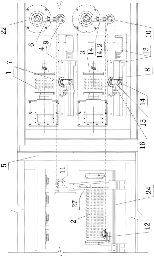
[0057] Such as figure 1 , figure 2 , image 3 , Figure 4 , Figure 5 , Figure 6 , Figure 7 Shown, the winding mechanism of diamond wire cutting machine of the present invention, it comprises and comprises pay-off roller 1, driving shaft 2, driven shaft (in front view, driven shaft is positioned at driving shaft rear, is blocked by it, but because driven shaft It is a mature prior art content, so it will not be described in detail), take-up roller 3 and diamond wire 4. The above-mentioned pay-off roller 1, driving shaft 2, driven shaft and take-up roller 3 are all installed on the frame 5 of the diamond wire cutting machine; and the pay-off roller 1, driving shaft 2, driven shaft and take-up roller 3 All driven by their own different motors. The pay-off roller 1 and the take-up roller 3 are both transverse.

[0058]The frame 5 is pr...


PUM


Abstract

The invention discloses a wire winding mechanism of a diamond wire cutting machine and a constant tension control method based on the wire winding mechanism. The wire winding mechanism comprises a wire unwinding roller, a driving shaft, a driven shaft, a wire winding roller, an upper moving module, a lower moving module, an upper swing arm, a lower swing arm, a first fixed guide wheel and a secondfixed guide wheel. A moving guide wheel is installed on each moving module, and a swing guide wheel is installed on each swing arm. A diamond wire is led out of the wire unwinding roller, passes through the first moving guide wheel, the first swing guide wheel and the first fixed guide wheel, then is wound around the driving shaft and the driven shaft to form a wire net, passes through the secondfixed guide wheel, the second swing guide wheel and the second moving guide wheel, and finally is led to the wire winding roller. The control method is characterized in that the feed-forward standardangular velocity wt calculated through feed-forward control and the angular velocity soft amplitude limiting treatment fine adjustment quantity dwl are superposed, so that the target angular velocitywy of each wire roller is acquired. The wire winding mechanism and the control method have the advantages that the number of the guide wheels can be reduced, the rigidity of the diamond wire can be improved, and the wire routing tension can be constant.

Description

technical field [0001] The invention relates to the field of cutting machinery and equipment, in particular to a winding mechanism of a diamond wire cutting machine and a constant tension control method based on the mechanism. Background technique [0002] In recent years, with the rapid development of the solar energy industry, the demand for hard and brittle materials such as monocrystalline silicon, polycrystalline silicon and piezoelectric ceramics has risen rapidly. As the main cutting equipment for hard and brittle materials such as solar silicon wafers, the diamond wire cutting machine has been more and more widely used due to its advantages of high cutting efficiency and good processing stability. [0003] The diamond wire cutting machine uses a winding mechanism to route wires to cut silicon materials. The winding mechanism of the diamond wire cutting machine in the prior art includes a vertical pay-off roller, a driving shaft, a driven shaft, a vertical take-up ro...

Claims


Application Information

Patent Timeline
IPC IPC(8): B28D5/04B28D7/00G05D15/01
CPCG05D15/01B28D5/0058B28D5/0064B28D5/045
Inventor 陈苍潘圣严宇婷戴健健谭志
Owner 宁波钜德精工机械有限公司
Why Eureka
Try Eureka