
Gas heating and hot water supply dual-purpose furnace system

A gas heating and hot water technology, applied in water heaters, fluid heaters, lighting and heating equipment, etc., can solve problems such as loud noise, heat waste, damage, etc., to reduce combustion noise, improve combustion efficiency, prevent Effects of high temperature damage

Pending Publication Date: 2018-05-08
NINGBO FOTILE KITCHEN WARE CO LTD
View PDF4 Cites 8 Cited by
  • Summary
  • Abstract
  • Description
  • Claims
  • Application Information

AI Technical Summary

Problems solved by technology

[0006] Existing burners all use shells made of metal plates. This shell has poor heat preservation effect, large heat loss, no energy saving, and high nitrogen oxides during combustion. The metal shell is easy to conduct noise. When the burner is working, the noise is large. ;Due to the poor heat preservation effect of the shell, it directly leads to the temperature rise around the shell, which will not only cause heat waste and low thermal efficiency, but also easily cause the internal electronic components of the hot water equipment (such as dual-purpose furnace) to attenuate or be damaged due to high temperature life , which seriously affects the service life of the hot water equipment; condensed water is easy to form around the combustion chamber, and the condensed water is easy to accumulate and form a water flow out of the shell

Method used


Image

  • Gas heating and hot water supply dual-purpose furnace system
  • Gas heating and hot water supply dual-purpose furnace system
  • Gas heating and hot water supply dual-purpose furnace system

Examples


Embodiment Construction

[0028] The present invention will be further described in detail below in conjunction with the accompanying drawings and embodiments.

[0029] Such as Figure 1-8 Shown is a preferred embodiment of the present invention.

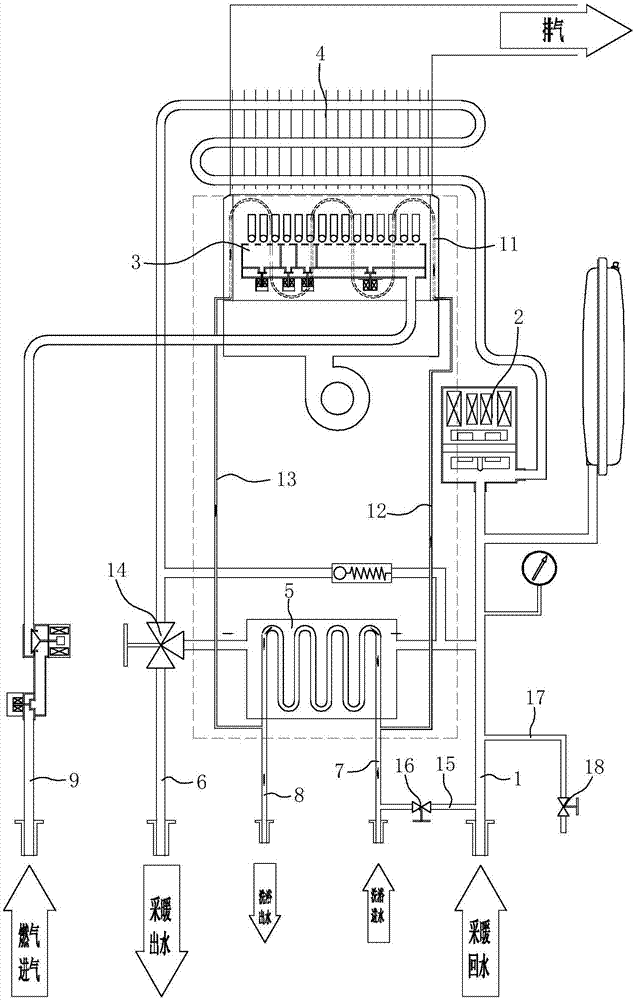
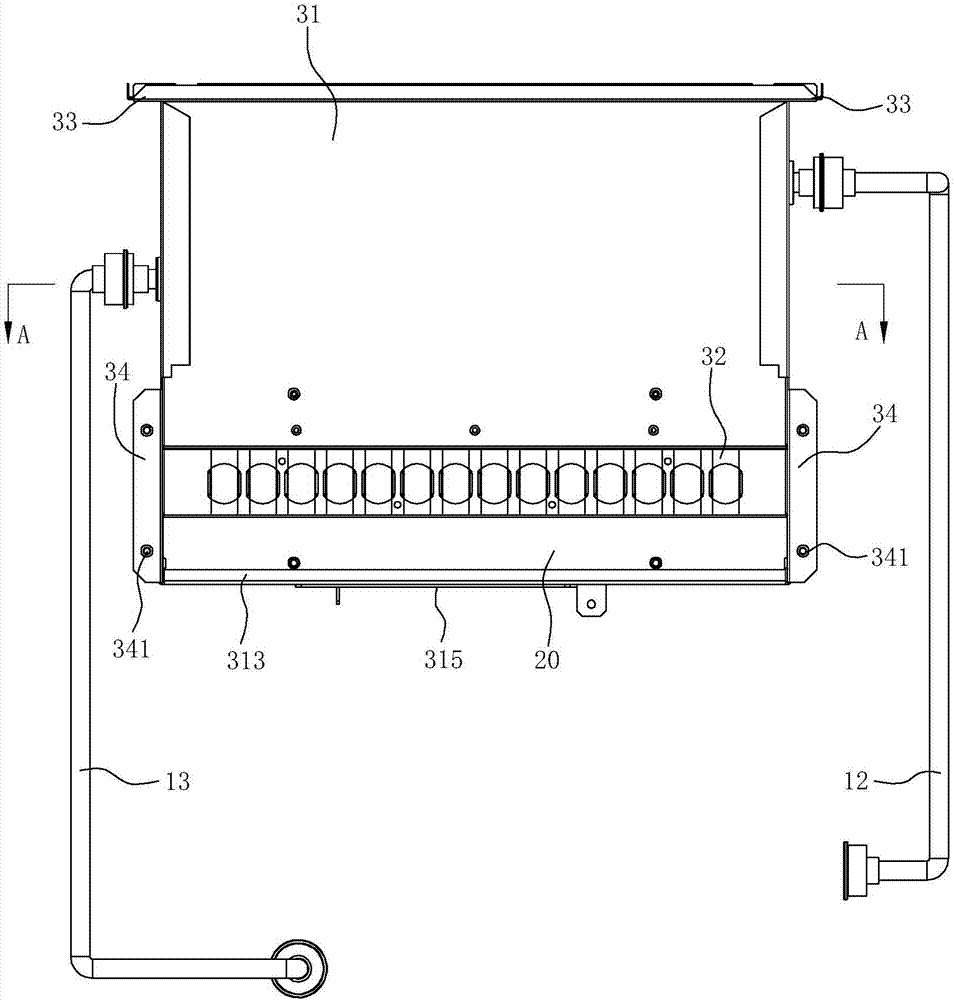
[0030] A gas heating and hot water dual-purpose boiler system, comprising a heating return pipe 1, a water pump 2, a gas burner 3, a combustion heat exchanger 4, a plate heat exchanger 5, a heating outlet pipe 6, a bath water inlet pipe 7, a bath Water outlet pipe 8; among them, the heating return pipe 1, the water pump 2, the combustion heat exchanger 4 and the heating outlet pipe 6 together form the heating water heating circuit, and the combustion heat exchanger 4, the plate heat exchanger 5, and the water pump 2 together form the bathing water The heating circuit, the bath water inlet pipe 7 and the bath water outlet pipe 8 communicate with the water inlet end and the water outlet end of the heat exchange tube in the plate heat exchanger 5 respectively....


PUM


Abstract

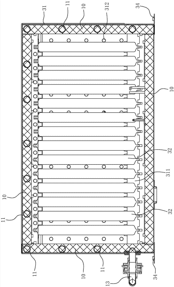
The invention relates to a gas heating and hot water supply dual-purpose furnace system. The gas heating and hot water supply dual-purpose furnace system comprises a heating water returning pipe, a water pump, a gas combustor, a combustion heat exchanger, a plate type heat exchanger, a heating water discharging pipe, a bathing water charging pipe and a bathing water discharging pipe; the gas combustor comprises a shell inside which a combustion chamber is formed; a fire grate plates are installed inside the combustion chamber; the gas heating and hot water supply dual-purpose furnace system ischaracterized in that at least the left part, the right part and the rear part of the inner wall of the combustion chamber are each provided with a heat insulating layer which is made from a heat insulating material; a position close to the left part, the right part and the rear part of the combustion chamber is provided with a heat absorbing water pipe; a water inlet of the heat absorbing waterpipe is connected with a bypass water charging pipe; a water outlet of the heat absorbing water pipe is connected with a bypass water discharging pipe; a water charging end of the bypass water charging pipe communicates with the bathing water charging pipe; and a water discharging end of the bypass water discharging pipe communicates with the bathing water discharging pipe. The gas heating and hotwater supply dual-purpose furnace system provided by the invention can fully utilize the heat generated by the combustor, can effectively reduce heat loss and can also reduce temperature increment and generation of condensate water around the combustor.

Description

technical field [0001] The invention relates to a gas heating device, in particular to a gas heating and hot water dual-purpose furnace system. Background technique [0002] The traditional gas heating and hot water dual-purpose boiler system uses a heat exchanger to absorb the heat generated by gas combustion, and transfers it to the heating water supplied by the circulating water pump. After heat exchange, the temperature of the heating water rises to form the heating water. , and then the heating outlet water provides heat to the heating system through the heating outlet pipe or supplies heat to the bathing water system through the plate heat exchanger. [0003] Such as Figure 9 As shown, the existing gas heating and hot water dual-purpose boiler system includes a heating return pipe, a water pump, a gas burner, a combustion heat exchanger, a plate heat exchanger, a heating outlet pipe, and a bathing water inlet pipe arranged in the casing. , Bathing water outlet pipe; ...

Claims


Application Information

Patent Timeline
IPC IPC(8): F24H1/40F24H1/48F24H9/00F24H9/18
CPCF24H1/40F24H1/48F24H9/0005F24H9/1836Y02B30/00
Inventor 杨开明周高云秦刚黄启彬茅忠群诸永定
Owner NINGBO FOTILE KITCHEN WARE CO LTD
Learn More