Surface shape measurement device and method based on structured light illumination

A technology of structured light illumination and measuring device, which is applied in the direction of measuring device, optical device, instrument, etc., can solve problems such as restricting the application of zoom surface shape measuring method.

Inactive Publication Date: 2018-05-08
HARBIN INST OF TECH
View PDF5 Cites 3 Cited by
  • Summary
  • Abstract
  • Description
  • Claims
  • Application Information

AI Technical Summary

Problems solved by technology

However, affected by background noise, for samples with low reflectivity and large reflectivity differences, the conventional method will introduce large errors, which restricts the application of the zoom surface shape measurement method

Method used


Image

  • Surface shape measurement device and method based on structured light illumination
  • Surface shape measurement device and method based on structured light illumination
  • Surface shape measurement device and method based on structured light illumination

Examples


Embodiment 1

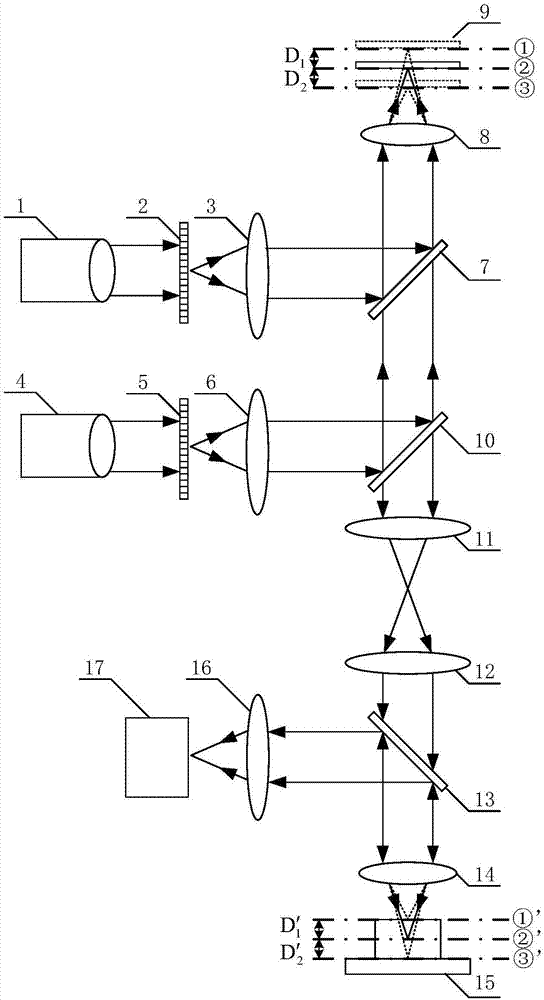
[0033] Embodiment 1: as attached figure 1 The illustrated embodiment provides a surface shape measurement device based on structured light illumination, which is used to quickly switch axial positions to realize three-dimensional tomographic scanning.

[0034] A surface shape measurement device based on structured light illumination, comprising a structured light illumination module, an axial scanning module and a detection module;

[0035] The structured light illumination module is composed of two illumination optical paths, the first illumination optical path is in order according to the light propagation direction: Kohler illumination module-1, amplitude type sinusoidal grating-2 and tube mirror-3; the second illumination optical path is according to the light propagation direction The propagation directions are: Kohler lighting module 2 4, amplitude type sinusoidal grating 2 5 and tube mirror 2 6;

[0036] According to one of the light propagation directions, the axial s...

Embodiment 2

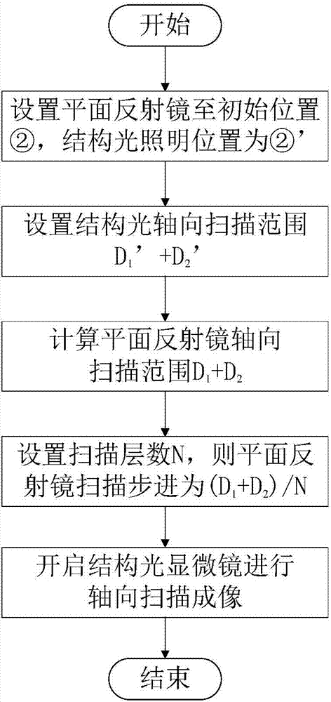
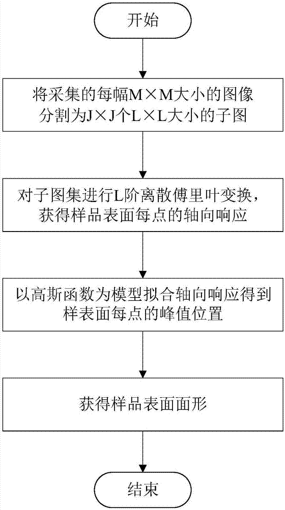
[0042] Embodiment 2: as attached figure 2 and image 3 The illustrated embodiment provides a surface shape measurement method based on structured light illumination, which is used to quickly switch axial positions to realize three-dimensional tomographic scanning.

[0043] A method for measuring surface shape based on structured light illumination, the method is implemented based on the surface shape measurement device based on structured light illumination described in Embodiment 1, and the specific steps are:

[0044] Data collection steps:

[0045] Step a, the Kohler lighting module 1 emits incoherent illumination light, which is modulated by the amplitude type sinusoidal grating 1 2 and exits from the tube lens 1 3 , at the same time, the Kohler illumination module 2 4 emits incoherent illumination light, passes through the amplitude type sinusoidal grating 2 5 After modulation, the two beams of illumination light are emitted by the tube mirror two 6, and the two beams of...


PUM


Abstract

A surface shape measurement device and a method based on structured light illumination belong to the optical microscopic imaging and measurement technology field. The device comprises a structured light illumination module, an axial scanning module and a detection module. An axial scanning device formed by a polarizing beam splitter, a low aperture objective lens, a pipe mirror, a plane reflectingmirror and the like is added in a conventional structured light illumination microscope system so as to realize high speed axial movement of structured light illumination stripes in an observed sample space. Window Fourier transform is used to process images shot under different z direction position stripe projections. A correlation coefficient of each subarea image at a projection stripe frequency is calculated and each horizontal position definition axial response curve is acquired. A peak value position of the curve is a relative height of a sample at a transverse position, and finally a sample surface shape is acquired. The device and the method possesses advantages that installation and adjustment are convenient; an axial scanning speed is fast; and an influence of a sample surface reflectivity difference on a measurement result is small and a signal to noise ratio is high.

Description

technical field [0001] The present invention relates to a surface shape measurement device and method, in particular to a surface shape measurement device and method based on structured light illumination, which can realize high-speed axial scanning of structured light illumination stripes in the observed sample space, and reduce background noise The influence of the reflectance difference with the surface second of the sample on the measurement result belongs to the field of optical microscopic imaging and surface shape measurement. Background technique [0002] The zoom surface shape measurement method obtains the surface shape of the sample surface by judging the imaging clarity of the measured sample at different axial positions within the field of view of the imaging objective lens. The conventional zoom surface measurement method uses the stage to drive the sample to scan axially, and the scanning speed is slow and the efficiency is low. Moreover, conventional methods...

Claims


Application Information

Patent Timeline
Patent Type & Authority Applications(China)
IPC IPC(8): G01B11/25
CPCG01B11/2518
Inventor 刘辰光郑婷婷谭久彬
Owner HARBIN INST OF TECH
Why Eureka
Try Eureka