Preparation method of high-speed tool steel

A high-speed tool steel and steel billet technology, applied in metal processing equipment, etc., can solve the problems of material processing cracks and mechanical property degradation, and achieve the effects of reducing liquid precipitation carbides, refining grains, and uniform mechanical properties

Active Publication Date: 2018-05-11
NORTHEASTERN UNIV
View PDF6 Cites 2 Cited by
  • Summary
  • Abstract
  • Description
  • Claims
  • Application Information

AI Technical Summary

Problems solved by technology

[0005] The purpose of the present invention is to provide a semi-solid thermal processing process that eliminates or reduces coarse liquefied carbides and refined grains in high-speed tool steel, and solves the problems caused by large liquefied carbides, coarse grains or mixed crystals in high-speed tool steel. Problems of processing cracks and mechanical property degradation of materials

Method used


Image

  • Preparation method of high-speed tool steel
  • Preparation method of high-speed tool steel

Examples


Embodiment 1

[0047] The weight of the experimental material M2 tool steel billet is 1 ton, and the specification is φ500×700mm. After chemical analysis, its specific composition is shown in Table 1.

[0048] The chemical composition of high-speed tool steel M2 in table 1 * embodiment 1 (weight percent, %)

[0049] element

C

Si

mn

S

P

Ni

Cr

Mo

Cu

V

W

Fe

Measured ingredients

0.85

0.035

0.25

≤0.03

≤0.04

≤0.03

4.10

5.0

0.1

1.90

6.40

Remain

[0050] *Liquidus T of this component L at 1445°C, the solidus T S It is 1245°C.

[0051] Semi-solid processing of M2 steel billet, the specific steps are as follows:

[0052] 1) Place a φ500×700mm billet in a crucible, heat up to 1465°C at a heating rate of 60°C / h, keep it warm for 1.5 hours, and then pour it out of the furnace into an iron mold.

[0053] 2) Cool the billet temperature to 1265°C at a cooling rate of 50°C / h, take it out of the iron mold ...

experiment example 1

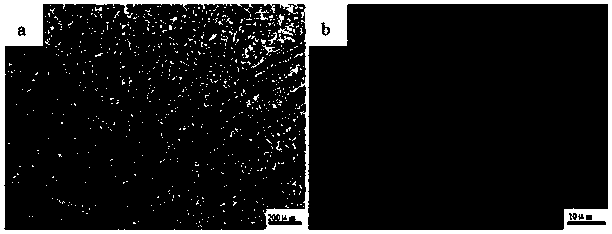
[0065] For Example 1 and Comparative Example 1, the metallographic microscope is used to analyze the sample structure state of the as-cast billet central region (250mm position below the surface), and the specific metallographic structure is shown in figure 1 (a), it can be seen that due to solidification segregation, there are a large number of dendrites and liquid carbides in the as-cast structure, and the specific morphology of carbides figure 1 (b), the main carbide types are MC, M6C and M2C.

[0066] Analyze the microstructure of the sample in the central area of ​​the billet after forging (150mm below the surface). For the specific metallographic structure, see figure 2 , it can be seen that after the conventional forging process is adopted, a large amount of liquid precipitated carbides still remain in the high-speed tool steel, and they are distributed in a network shape ( figure 2 (a)), while using the large deformation process in the solid-liquid two-phase region ...


PUM


Abstract

The invention relates to the field of hot working of steel and relates to a preparation method of high-speed tool steel. The preparation method of the high-speed tool steel comprises the following technological steps that (1) a to-be-treated ledeburite high-speed tool steel billet material is heated to a temperature above TL (liquidus temperature), and is molten fully; (2) the ledeburite high-speed tool steel billet material is cooled to a temperature in a solid-liquid two-phase region between the TL and TS (solidus temperature), heat preservation is carried out, and thus a semisolid structurewith the solid-phase rate being above 70% is obtained; (3) the ledeburite high-speed tool steel billet material is subjected to deformation with the forging ratio being above 1.5 in the solid-liquidtwo-phase region; and (4) the ledeburite high-speed tool steel billet material is cooled to a temperature below the TS, an operator continues to carry out the deformation with the forging ratio beingabove 1.5, and thus the high-speed tool steel is obtained. By carrying out the deformation in the solid-liquid two-phase region, nascent dendritic crystals in the high-speed tool steel solidificationprocess can be broken effectively, dendritic segregation is relieved, precipitation of liquation carbides is inhibited, and the purposes of obtaining a homogenized structure, improving comprehensive mechanical properties and prolonging the service life are achieved.

Description

technical field [0001] The invention relates to the field of thermal processing of steel, and relates to a preparation method of high-speed tool steel, specifically a semi-solid thermal processing process for eliminating or reducing coarse liquefied carbides and refining grains of high-speed tool steel, which is used to solve the problem of In high-speed tool steels, large pieces of liquefied carbides, coarse grains or mixed grains lead to the degradation of mechanical properties of materials. Background technique [0002] With its good formability and excellent mechanical properties, iron and steel materials affect all aspects of human production and life, and are the most successful and popular metal materials in human history. Human beings have never stopped exploring the smelting and processing technology of iron and steel materials. In recent years, with the modernization and high-speed development of my country's transportation industry and weapons and equipment, high...

Claims


Application Information

Patent Timeline
Patent Type & Authority Applications(China)
IPC IPC(8): B22D18/02B21J5/00
CPCB21J5/004B22D18/02
Inventor 贾鹏王恩刚
Owner NORTHEASTERN UNIV
Why Eureka
Try Eureka