
Flowing water destruction sieving test device and method

A testing device, water disintegration technology, applied in the direction of removing a certain component and weighing, etc., can solve the problems of invisibility, mechanical interference, changes in the test process, etc., and achieve the effect of simple and practical design, easy movement, and accurate testing.

Active Publication Date: 2018-05-11
SHIJIAZHUANG TIEDAO UNIV
View PDF9 Cites 2 Cited by
  • Summary
  • Abstract
  • Description
  • Claims
  • Application Information

AI Technical Summary

Problems solved by technology

[0003] The object of the present invention is to provide a dynamic water disintegration screening test device and method, which has the characteristics of accurate test, simple and practical design, small weight and easy movement, and can conduct more accurate and more practical rock disintegration tests. To solve the above-mentioned background technology, the rotation of the disintegration barrel of the existing instrument in the test process causes the sample to receive relatively large mechanical interference, which does not conform to the actual situation; it is not possible to quantitatively simulate the disintegration rate under the action of different dynamic water rates; and The change in the test process is invisible; the sieve disc used has only a single particle size, which cannot meet the requirements of measuring the quality change of rock disintegration with different particle sizes

Method used


Image

  • Flowing water destruction sieving test device and method
  • Flowing water destruction sieving test device and method
  • Flowing water destruction sieving test device and method

Examples


Embodiment Construction

[0026] The following will clearly and completely describe the technical solutions in the embodiments of the present invention with reference to the accompanying drawings in the embodiments of the present invention. Obviously, the described embodiments are only some, not all, embodiments of the present invention. Based on the embodiments of the present invention, all other embodiments obtained by persons of ordinary skill in the art without making creative efforts belong to the protection scope of the present invention.

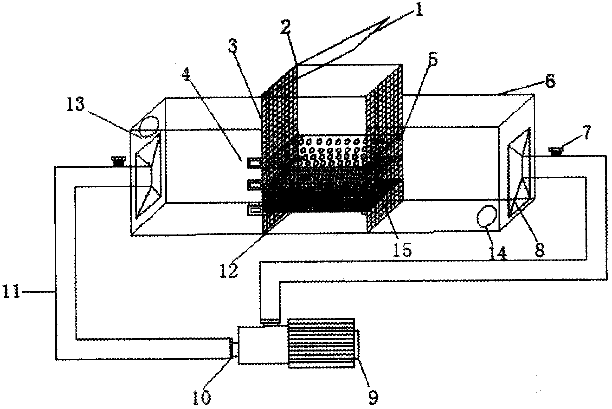
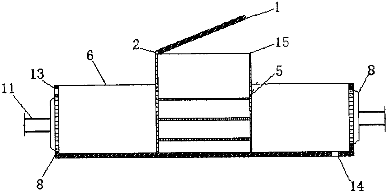
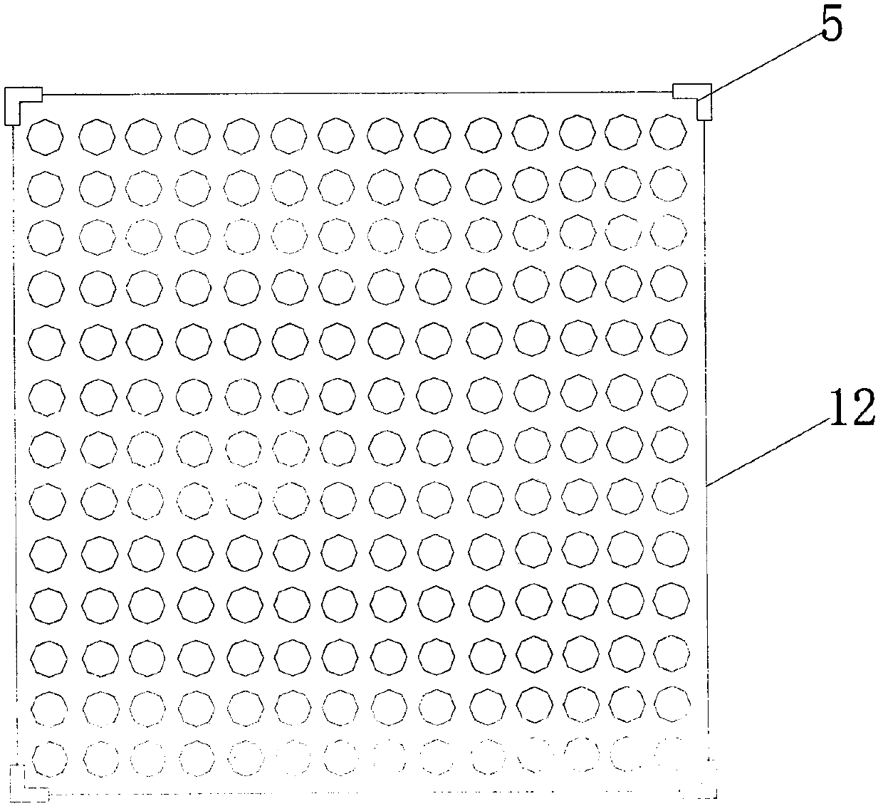
[0027] see Figure 1-3 , in the embodiment of the present invention: a dynamic water disintegration and screening test device, including a disintegration and screening test bucket, a dynamic water diversion device and a circulating water pump system; the disintegration and screening test bucket includes a test bucket cover 1 and a rotating shaft 2 , the test barrel frame 3, the sieve plate 12, the filter screen 15, and the card slot 5, the test barrel cover 1 ...


PUM


Abstract

The invention discloses a flowing water destruction sieving test device and method. The device includes a destruction sieving test barrel, a flowing water guiding device and a circulating water pump system; the destruction sieving test barrel includes a testing barrel framework, a clamping slot, a sieving disc, a testing barrel cover, a filtering screen and the like; the flowing water guiding device comprises a flow guiding groove, a water inlet, a water outlet and a sprayer, and the flow guiding groove is bonded with the framework of the destruction sieving test barrel through water-resistantglue; the sprayer is arranged between a water guiding groove and a guiding pipe in order to make a water flow in the flow guiding groove close to a laminar flow. The circulating water pump system includes a water pump, a water pump valve and the guiding pipe. Through the water pump, power is provided for water, and the flow guiding groove serves as a buffering strip. According to different waterpumping powers of the water pump, the flow speed can be quantitatively controlled, the destruction speed rates under different flow speeds and sieved objects different in granule size are obtained, the specific gravity occupied by each destructed object different in granule size is precisely measured, and the flowing water destruction sieving test device has the advantages of being accurate in measurement, simple and practical in design, light in weight and convenient to move.

Description

technical field [0001] The invention relates to the technical field of civil engineering tests, in particular to a hydrodynamic disintegration screening test device and method. Background technique [0002] The ability of rock to resist softening and disintegration under dynamic water conditions is a problem that must be considered in geotechnical or rock engineering, and the rock disintegration resistance test is the main method for determining the softening and disintegration ability of rock soil or rock samples under certain simulated conditions. method. At present, the equipment used by most scientific research or colleges and universities in my country to measure the disintegration index is the rock disintegration tester, which has many limitations and relatively large defects in its use. The specific performance is: during the test process, the rotation of the disintegration barrel caused the sample to receive a large mechanical interference, which did not conform to ...

Claims


Application Information

Patent Timeline
Patent Type & Authority Applications(China)
IPC IPC(8): G01N5/04
CPCG01N5/04
Inventor 王伟贾泽钰袁维闻磊常江芳刘学宁马佳骥樊宏宇张明涛刘亚男
Owner SHIJIAZHUANG TIEDAO UNIV
Learn More