Film thickness measuring device and film thickness measuring method

A technology for measuring devices and film thickness, which is applied in the direction of measuring devices, optical devices, instruments, etc., can solve the problems of not performing film thickness inspection, and achieve the effect of easy film thickness distribution

Active Publication Date: 2018-05-11
DAINIPPON SCREEN MTG CO LTD +1
View PDF10 Cites 8 Cited by
  • Summary
  • Abstract
  • Description
  • Claims
  • Application Information

AI Technical Summary

Problems solved by technology

[0007] In addition, in Patent Document 3 and Patent Document 4, both the positive electrode and the negative electrode are adjusted using the weight per unit area as the monitoring amount for both the positive electrode and the negative electrode, but the film thickness inspection after the coating process, etc. are not performed.

Method used


Image

  • Film thickness measuring device and film thickness measuring method
  • Film thickness measuring device and film thickness measuring method
  • Film thickness measuring device and film thickness measuring method

Examples


no. 1 approach

[0059]

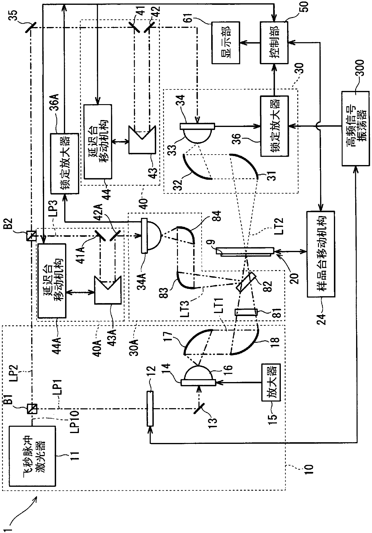
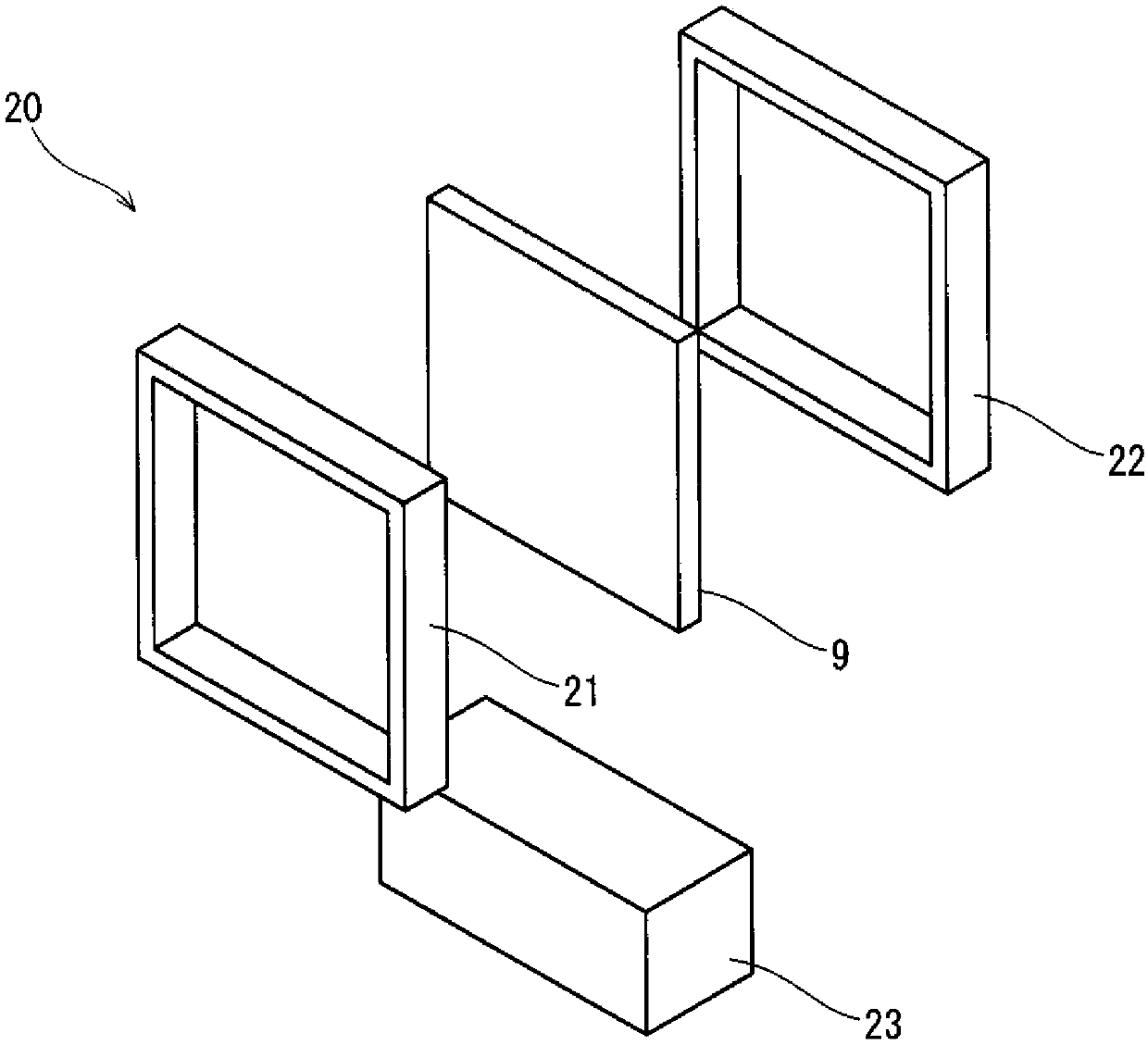
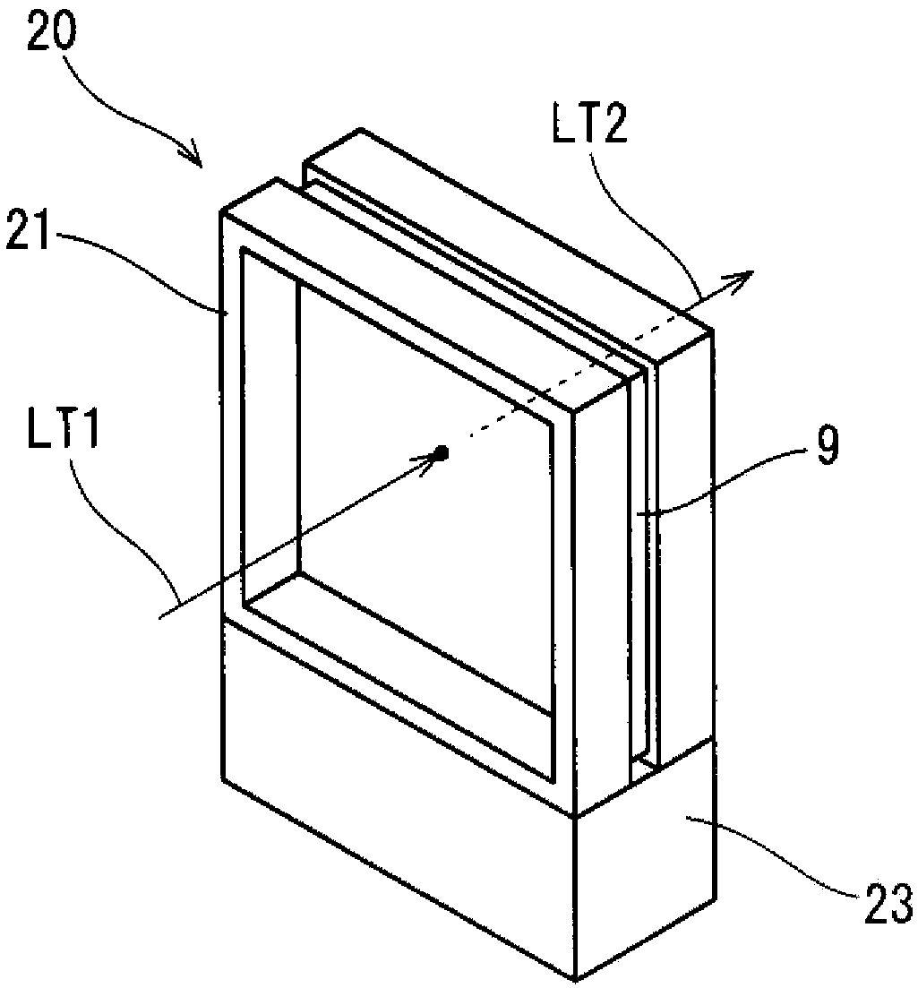
[0060] figure 1 It is a schematic configuration diagram showing the film thickness measurement device 1 of the first embodiment. Such as figure 1 As shown, the film thickness measurement device 1 includes a terahertz wave irradiation unit 10 , a sample stage 20 , a transmitted wave detection unit 30 , a reflected wave detection unit 30A, delay units 40 and 40A, and a control unit 50 . The transmitted wave detection unit 30 and the delay unit 40 constitute a refractive index acquisition system provided for acquiring the refractive index of a film containing an active material material (hereinafter referred to as “active material film”). In addition, the reflected wave detection unit 30A and the delay unit 40A constitute a film thickness measurement system provided for measuring the film thickness of the active material film.

[0061]

[0062] The terahertz wave irradiation unit 10 is configured to irradiate the sample 9 supported by the sample stage 20 with a ter...

no. 2 approach

[0172] Figure 18 It is a schematic side view showing an active material film forming system 100 incorporating the film thickness measuring device 1A of the second embodiment. The active material film forming system 100 is a system for forming the active material film 91 on one surface of a sheet-shaped current collector 93 conveyed in a roll-to-roll manner. This active material film forming system 100 includes a film thickness measurement device 1A that measures the film thickness of the active material film in the middle of the conveyance path of the current collector 93 .

[0173] In the active material film forming system 100 , the current collector 93 unwound from the unwinding roller 701 is conveyed to the coating unit 71 via the conveyance rollers 702 and 703 .

[0174] The coating unit 71 has a slit die 711 , a coating liquid supply unit 713 , and a backup roll 715 . The slit die 711 has a slit-shaped discharge port extending in the width direction of the current col...


PUM


Abstract

Provided is a technique for performing a film thickness inspection on a film including an active material formed on a current collector in a non-contact manner during a process of manufacturing a lithium-ion battery. This film thickness measuring device 1 is provided with: a terahertz wave emission unit 10 that emits a terahertz wave LT1 to a sample 9; and a reflected wave detection unit 30A provided with a photoconductive switch 34A that detects reflected waves LT3 of the terahertz wave LT1 reflected at the sample 9. The film thickness measuring device 1 is provided with: a time difference acquisition module 509 that acquires a time difference [delta]t required to reach the photoconductive switch 34A between of the reflected waves LT3 detected by the reflected wave detection unit 30A a surface reflected wave LT31 reflected at the surface of an active material film 91 in the sample 9 and an interface reflected wave LT32 reflected at the interface between the active material film 91 andthe current collector 93 in the sample 9; and a film thickness calculation unit 511 that calculates the film thickness d of the active material film 91 on the basis of the time difference [delta]t and the refractive index nS of the active material film 91.

Description

technical field [0001] The present invention relates to a technique for measuring the film thickness of an active material material film formed on a current collector. Background technique [0002] A lithium ion secondary battery (LiB) is composed of a positive electrode, a negative electrode, and a separator configured to separate the positive electrode from the negative electrode to prevent electrical short-circuiting between the positive electrode and the negative electrode. The positive electrode is formed by coating a metal active material such as lithium cobaltate, conductive graphite (carbon black, etc.), and a binder resin on a current collector such as aluminum foil. In addition, the negative electrode is constituted by coating graphite (natural graphite, artificial graphite, etc.) and a binder resin as an active material on a current collector such as aluminum foil. In addition, the separator is composed of a polyolefin-based insulating film or the like. The posi...

Claims


Application Information

Patent Timeline
Patent Type & Authority Applications(China)
IPC IPC(8): G01B15/02G01B11/06
CPCG01B11/06G01B15/02
Inventor 高濑惠宏中西英俊木濑一夫河野元宏川山巌斗内政吉
Owner DAINIPPON SCREEN MTG CO LTD
Why Eureka
Try Eureka