Photovoltaic power generation system

A photovoltaic power generation system and photovoltaic module technology, applied in photovoltaic power generation, photovoltaic modules, photovoltaic module support structures, etc., can solve the problems of high price and high cost of use, and achieve the goals of improving power generation efficiency, facilitating manufacturing and processing, and reducing photovoltaic voltage Effect

Inactive Publication Date: 2018-05-15
李会欣 +1
View PDF5 Cites 3 Cited by
  • Summary
  • Abstract
  • Description
  • Claims
  • Application Information

AI Technical Summary

Problems solved by technology

[0005] The purpose of the present invention is to provide a photovoltaic power generation system to...

Method used


Image

  • Photovoltaic power generation system
  • Photovoltaic power generation system
  • Photovoltaic power generation system

Examples


Embodiment 1

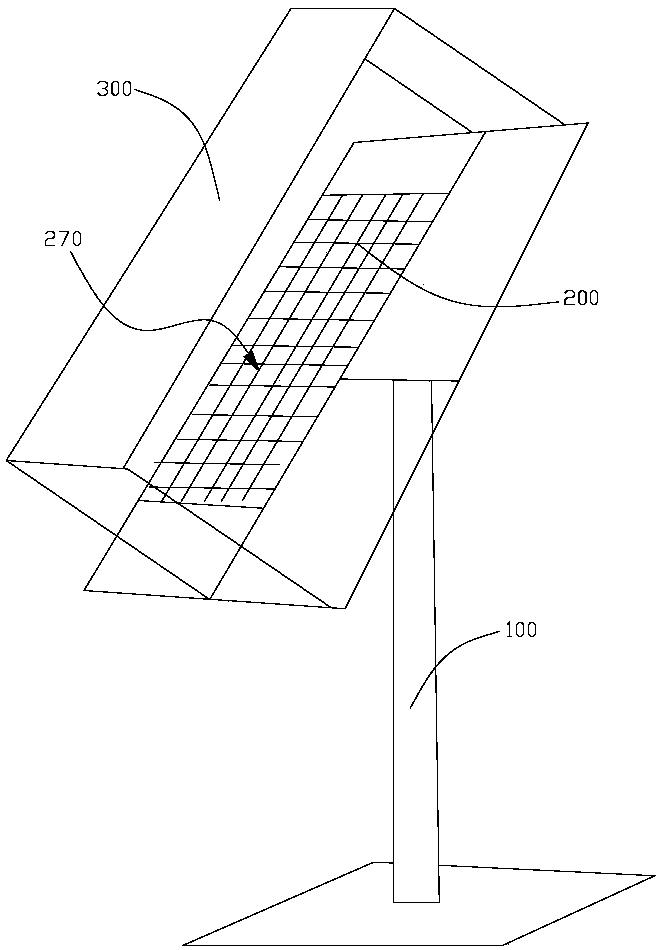
[0044] see figure 1 , this embodiment provides a photovoltaic power generation system.

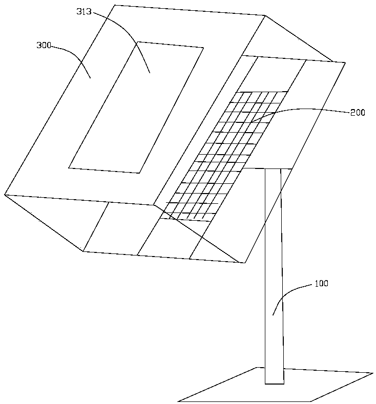
[0045] The photovoltaic power generation system provided in this embodiment includes a frame 100, a photovoltaic module 200, a light-shifting component 300, and a heat-insulating and light-transmitting layer 400. The photovoltaic component 200 and the light-shifting component 300 are installed on the frame 100, and the light-shifting component 300 is set on the side where the sun-facing surface 270 of the photovoltaic module 200 is located, and the heat-insulating and light-transmitting layer 400 is set on the side where the sun-facing surface of the photovoltaic module 200 is located. The cells for photovoltaic electronic components can reduce the photovoltaic voltage of photovoltaic components.

[0046] In other words, the photovoltaic power generation system provided in this embodiment is a low-temperature high-light photovoltaic power generation system, and the low-temperature high-li...

Embodiment 2

[0063] see Figure 4 , this embodiment also provides a photovoltaic power generation system, this embodiment is a further improvement on the basis of the technical solution of embodiment 1, the technical solution already described in embodiment 1 is also applicable to this embodiment, in order to avoid The description is redundant, and the technical solution disclosed in Embodiment 1 will not be described in detail again.

[0064] see Figure 8 - Figure 9 , in this embodiment, the heat-insulating and light-transmitting layer 400 is installed on the dust-removing glass 260, and the heat-insulating and light-transmitting layer 400 can be painted on the outer surface or the inner surface of the dust-removing glass 260, or the heat-insulating and light-transmitting layer 400 can be directly It is integrally formed with the dust-removing glass, and the material for making the heat-insulating light-transmitting layer 400 and the material of the dust-removing glass are mixed and the...


PUM


Abstract

The invention provides a photovoltaic power generation system including a photovoltaic module, a heat insulation and light transmission layer, and a light shift component. The heat insulation and light transmission layer is directly installed on the light shift component, or a heat insulation and light transmission material is made on the original photovoltaic glass of the photovoltaic module, orthe heat insulation and light transmission material is made on the EVA of the phototropic face of the photovoltaic module. The light shift component is arranged on the side where the non-phototropic face of the photovoltaic module is located or at the periphery of the non-phototropic face of the photovoltaic module. The photovoltaic power generation system includes a heat insulation and light transmission material. In the actual working process of the photovoltaic power generation system, the sunlight directly irradiated on the photovoltaic module is directly irradiated on the photovoltaic module, and the sunlight within a certain range around the photovoltaic module which cannot be irradiated on the photovoltaic module is also irradiated on the photovoltaic module through the light shiftcomponent. Therefore, the photoelectric conversion efficiency of the photovoltaic power generation system is greatly improved, the cost is reduced, and the conversion efficiency of optical energy is higher.

Description

technical field [0001] The present invention relates to the technical field of photovoltaic power generation, in particular to a photovoltaic power generation system. Background technique [0002] The energy problem has become a worldwide problem, and making full use of solar energy has become an inevitable trend. At present, there are many solar photoelectric conversion technologies, and the technology is mature and has been used for power generation mainly silicon-based photovoltaic solar modules (hereinafter referred to as photovoltaic modules), this energy is clean and environmentally friendly, but the conversion rate of this module is too low and the cost is too high , which hampers its development in many ways. People have been trying to solve this problem for 60 years. [0003] In addition to crystalline silicon components, people are still developing thin film components, and people use a variety of materials, inorganic and organic. Such as: use gallium arsenide, ...

Claims


Application Information

Patent Timeline
IPC IPC(8): H02S40/20H02S40/22H02S20/10H01L31/048
CPCY02E10/52H02S40/20H01L31/048H02S20/10H02S40/22
Inventor 李会欣闫树林
Owner 李会欣
Why Eureka
Try Eureka