
Thermal forming device

A thermoforming and accommodating groove technology, applied in the field of machining, can solve the problems of shortening the service life of the mold, damage to the punch insert, and rising production costs, so as to improve the product yield, prolong the service life, and achieve consistent tensile strength. the effect of strength

Inactive Publication Date: 2018-05-18
ZHEJIANG GEELY AUTOMOBILE RES INST CO LTD +1
View PDF7 Cites 1 Cited by
  • Summary
  • Abstract
  • Description
  • Claims
  • Application Information

AI Technical Summary

Problems solved by technology

[0008] 1. The production efficiency is limited, and the production cycle is limited by the cooling time of the slowest cooling plate
[0009] 2. The yield rate is low, and the slow cooling rate of the sheet metal will inevitably cause incomplete transformation of martensite, so that the overall strength of the part will be uneven and affect the tensile strength of the part
[0010] 3. Part of the insert of the punch is damaged. When the slowest-cooling sheet can meet the strength conditions for demoulding, the fast-cooling sheet will "tightly" hold the punch because of its low temperature and thermal expansion. The 1500MPa hot-formed steel plate is easy to pull out the punch insert and damage the mold, shortening the service life of the mold
When the damage reaches a certain level, the insert needs to be replaced, resulting in an increase in production cost
[0011] From the above analysis, it can be seen that the existing hot stamping dies have many defects, and it is urgent to optimize their structure

Method used


Image

  • Thermal forming device
  • Thermal forming device
  • Thermal forming device

Examples


Embodiment 1

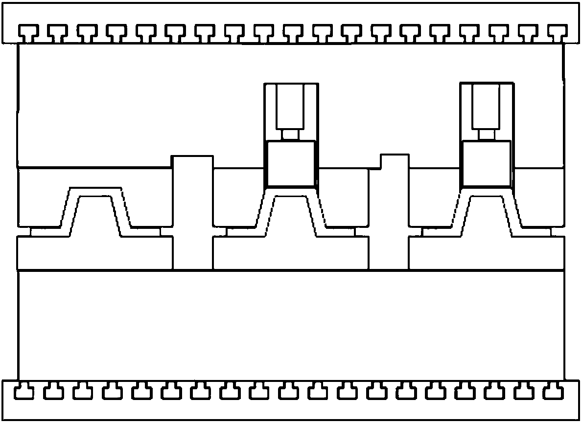
[0044] This embodiment provides a thermoforming device, such as Figure 5 As shown, the device 2 includes a first substrate 1, a second substrate 3, and a plurality of molds 2 arranged between the first substrate 1 and the second substrate 3. See Image 6 Each mold 2 includes an upper mold 21 and a lower mold 23 that cooperate with each other. The upper mold 21 includes an upper mold base 211 and an upper mold body. The lower mold 23 includes a lower mold base 231 and a lower mold body. The mold base 211 is mounted on the first substrate 1, the top of the upper mold 21 body is connected to the upper mold base 211, the lower mold base 231 is mounted on the second base plate 3, and the lower mold The bottom of the body is connected to the lower mold base 231, and a cavity for accommodating the workpiece 22 is formed between the bottom of the upper mold 21 and the top of the lower mold 23; the upper mold body and the upper mold base 211 is fixedly connected, the lower mold body ha...

Embodiment 2

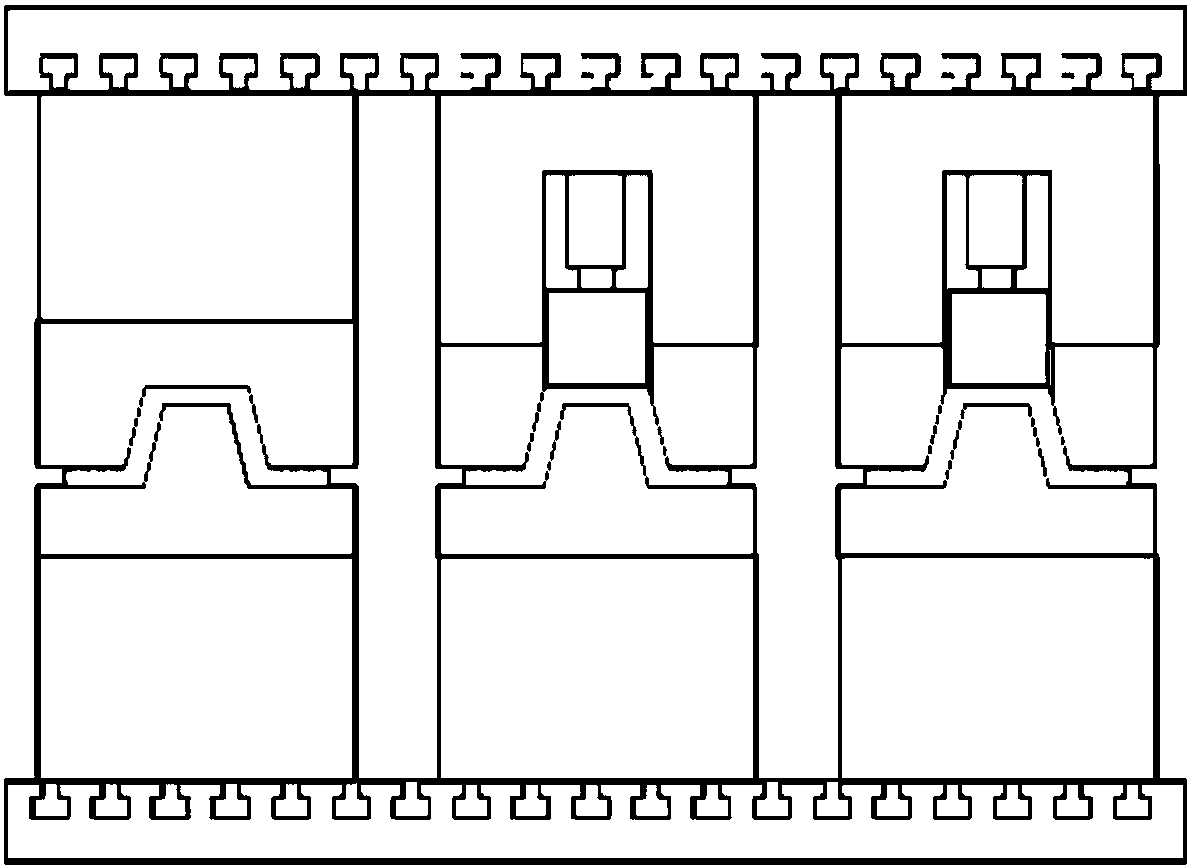
[0057] This embodiment provides a thermoforming device, such as Figure 7 As shown, the device 2 includes a first substrate 1, a second substrate 3, and a plurality of molds 2 arranged between the first substrate 1 and the second substrate 3. See Image 6 Each mold 2 includes an upper mold 21 and a lower mold 23 that cooperate with each other. The upper mold 21 includes an upper mold base 211 and an upper mold body. The lower mold 23 includes a lower mold base 231 and a lower mold body. The mold base 211 is mounted on the first substrate 1, the top of the upper mold 21 body is connected to the upper mold base 211, the lower mold base 231 is mounted on the second base plate 3, and the lower mold The bottom of the body is connected to the lower mold base 231, and a cavity for accommodating the workpiece 22 is formed between the bottom of the upper mold 21 and the top of the lower mold 23; the lower mold body and the lower mold base 231 is fixedly connected, the upper mold body ha...


PUM


Abstract

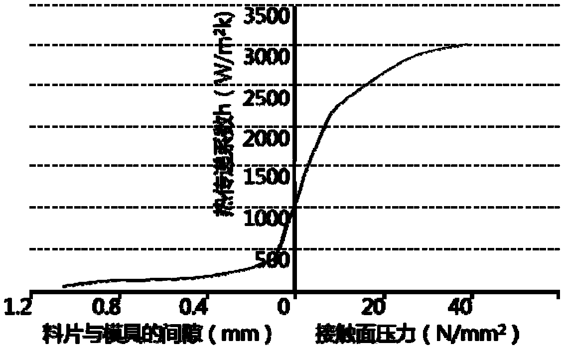
The invention relates to the field of machining, in particular to a thermal forming device. The device comprises a first substrate, a second substrate and a plurality of molds arranged between the first substrate and the second substrate, each mold comprises an upper mold and a lower mold which cooperate with each other, the upper molds comprise upper mold bases and upper mold bodies, and the lower molds comprise lower mold bases and lower mold bodies; the upper mold bases are installed on the first base plate, the tops of the upper mold bodies are connected with the upper mold bases, the lower mold bases are installed on the second base plate, and the bottoms of the lower mold bodies are connected with the lower mold bases, and mold cavities for accommodating workpieces are formed betweenthe bottoms of the upper mold bodies and the tops of the lower mold bodies; and the upper mold bodies or the lower mold bodies are provided with movable parts, and the movable parts are used for changing the sizes of the mold cavities, so that contact pressure between the surface of the mold cavity of each mold in the device and the surface of the corresponding workpiece tends to be consistent. According to the thermal forming device, production efficiency and the product yield of machining multiple workpieces at the same time can be improved.

Description

Technical field [0001] The invention relates to the field of mechanical processing, in particular to a thermoforming device. Background technique [0002] Molds, various molds and tools used in industrial production to obtain the required products by methods such as injection molding, blow molding, extrusion, die-casting or forging molding, smelting, and stamping. In short, a mold is a tool used to shape an article. This tool is composed of various parts, and different molds are composed of different parts. It mainly realizes the processing of the shape of the article by changing the physical state of the molded material. [0003] At present, the hot forming molds used by major hot stamping parts suppliers are produced by multiple sheets, and generally adopt the form of one mold with multiple cavities or a combination of multiple molds. The structure of a multi-cavity thermoforming mold is as follows figure 1 As shown, the structure of the thermoforming mold installed in combinati...

Claims


Application Information

Patent Timeline
Patent Type & Authority Applications(China)
IPC IPC(8): B21D37/10B21D37/16B21D22/02
CPCB21D37/10B21D22/022B21D37/16
Inventor 卢磊王健江克洪郝勤
Owner ZHEJIANG GEELY AUTOMOBILE RES INST CO LTD
Learn More