Supercharge Your Innovation With Domain-Expert AI Agents!

A method for processing a casing assembly of a turbine case

A technology of turbine case and shell assembly, which is applied in the direction of engine components, mechanical equipment, machines/engines, etc. It can solve the problems of unsure of the angular position of the welding heat shield, chip breaking, sealing cavity, and inability to clean, etc., to improve Processing accuracy and product qualification rate, improve processing quality, and improve the effect of processing quality

Active Publication Date: 2019-05-14
CHINA HANGFA GUIZHOU LIYANG AVIATION POWER CO LTD
View PDF8 Cites 0 Cited by
  • Summary
  • Abstract
  • Description
  • Claims
  • Application Information

AI Technical Summary

Problems solved by technology

The 72 slanted ventilation holes on the turbine casing must correspond one-to-one with the ventilation holes on the heat shield to be welded. The heat shield is a strip with a thickness of only 0.2mm to 0.3mm, and the material is GH3030. The combined processing after welding will not only The sealing plate is extruded and deformed, and there will be burrs and iron filings on the cavity between the casing and the sealing plate, which cannot be cleaned. At the same time, due to the lack of hole positioning, its angular position cannot be determined when welding the heat shield
Therefore, the vent hole must be machined to size before welding, which reduces the burrs on the cavity of the casing and the sealing plate. However, since the front end of the casing is used as the reference plane of the casing and the casing, the precision requirements are extremely high. High, in order to ensure the overall processing quality of the casing and meet the requirements of the design drawing, it is necessary to reserve a margin on the front face for combined processing, which brings the problem of chip breaking processing and the risk of excess in the sealing cavity

Method used


Image

  • A method for processing a casing assembly of a turbine case
  • A method for processing a casing assembly of a turbine case

Examples


Embodiment Construction

[0039] The technical scheme of the present invention will be further described below in conjunction with the accompanying drawings, but the required protection scope is not limited to the description;

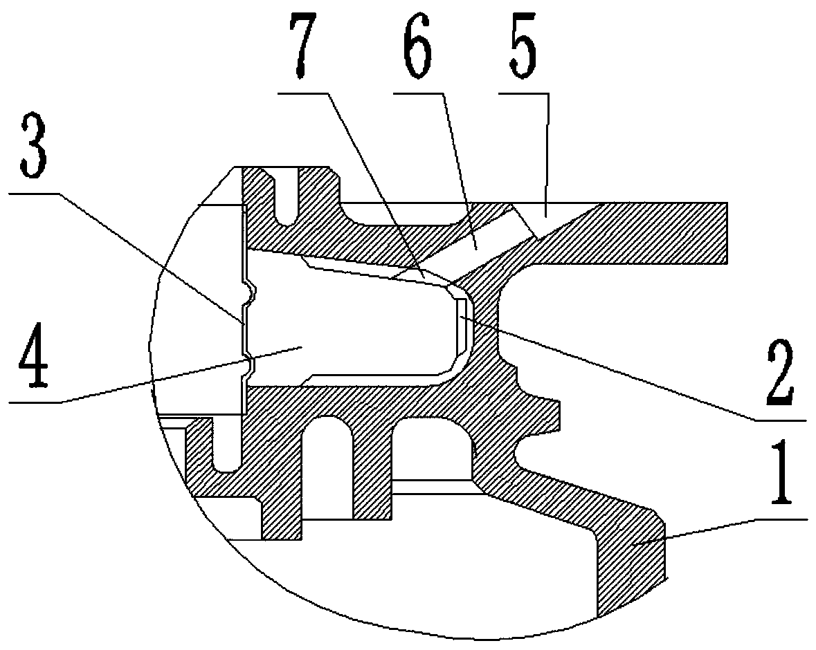
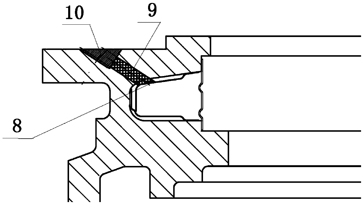
[0040] The invention provides a method for processing a casing assembly of a turbine case, such as Figure 1 to Figure 2 shown, including the following steps:

[0041] Step 1: Prepare the turbine case shell 1, heat shield 2 and seal plate 3: the inner wall of the turbine case shell 1 is provided with a seal cavity 4, the heat shield 2 is provided with a connecting hole 7, and the shape of the seal plate 3 is larger than that of the seal The port of cavity 4; further, the casing of the turbine casing is thin-walled made of high temperature resistant alloy material, the number of connecting holes is 972, and the diameter is φ0.8mm. The heat shield is a strip with a thickness of 0.2 mm to 0.3 mm, and the material is GH3030, which further reduces the transmission of the cutting ed...


PUM


Abstract

The invention relates to a machining method of a turbine case shell module. The machining method comprises preparation of a turbine case shell, a thermal insulation plate and a sealing plate; a sealing cavity is formed in the inner wall of the turbine case shell; a ventilation hole and a ventilation counter bore are machined on the end surface of the turbine case shell for communicating the sealing cavity with the end surface of the turbine case shell; corresponding protective materials are filled in a connecting hole, the ventilation hole and the ventilation counter bore; all shape characteristics at the periphery of the sealing cavity of the turbine case shell are machined; and finally, the internal of the sealing cavity is cleaned. The machining method prevents welding slag, iron chipsand like generated in the welding process from invading into the sealing cavity to stop transfer of cutting heat into the sealing cavity in the cutting process, maintains cleanness in the sealing cavity, reduces heated deformation in the sealing cavity, improves the machining quality and protective measures, is simple in structure, convenient to operate and stable and reliable in use, saves the machining time, and improves the machining precision and the product pass percent.

Description

technical field [0001] The invention relates to the technical field of mechanical processing, in particular to a processing method for a casing assembly of a turbine casing. Background technique [0002] In recent years, the machinery and equipment manufacturing industry has developed rapidly. People have designed and manufactured a variety of machinery and equipment to facilitate people's production, life and other activities. Machinery and equipment are composed of parts of different shapes, sizes and functions. , the turbine casing is an important high-temperature load-bearing part on an aero-engine. Its main working principle is that the pressure gas pushes the rotor to rotate. The machining quality of the turbine casing affects the assembly quality of the engine. Difficulties in processing such as easy deformation are a major problem in processing; for example, on a certain type of aero-engine, the turbine casing is composed of the turbine casing shell, the bushing weld...

Claims


Application Information

Patent Timeline
Patent Type & Authority Patents(China)
IPC IPC(8): B23P15/00
CPCB23P15/00F01D25/145
Inventor 胡鹏林洪芝张元伟庄丹文光泽
Owner CHINA HANGFA GUIZHOU LIYANG AVIATION POWER CO LTD
Features
  • R&D
  • Intellectual Property
  • Life Sciences
  • Materials
  • Tech Scout
  • Unparalleled Data Quality
  • Higher Quality Content
  • 60% Fewer Hallucinations
Learn More