Magnetron sputtering inlet sealing flange of magnetron sputtering machine

A magnetron sputtering and inlet sealing technology, applied in the direction of engine sealing, sputtering coating, mechanical equipment, etc., can solve the problems of cold slip deformation, chronic failure, chronic sealing failure, etc., to reduce pressure, seal reliable, The effect of high sealing reliability

Active Publication Date: 2018-05-18
10TH RES INST OF CETC
View PDF8 Cites 0 Cited by
  • Summary
  • Abstract
  • Description
  • Claims
  • Application Information

AI Technical Summary

Problems solved by technology

The wire thread insert designed abroad has only 38 thread inserts, and the nesting depth is 0.23mm. There is no problem when it is used for steel parts, but it is reasonable to cause chronic failure of the seal when it is used for soft plastic and tension-bearing components.
Our emergency design adopts the form of T-shaped nuts, one end of which is a protruding disc, which forms a certain area of ​​pressure on the soft plastic after being stressed, and is tightened with a torque wrench. As a result, a review after 1 year found that the overall tightening torque dropped by 24%. , the tightening torque of individual bolts decreased by 33%, and the material suffered severe cold-slip deformation after being subjected to alternating heating during use, and chronic failure still existed

Method used


Image

  • Magnetron sputtering inlet sealing flange of magnetron sputtering machine
  • Magnetron sputtering inlet sealing flange of magnetron sputtering machine
  • Magnetron sputtering inlet sealing flange of magnetron sputtering machine

Examples


Embodiment Construction

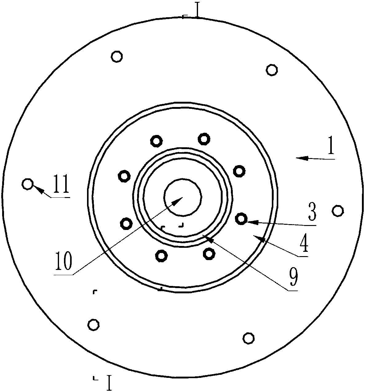
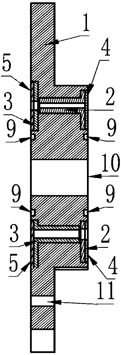
[0023] exist figure 1 In the shown embodiment, a magnetron sputtering inlet sealing flange of a magnetron sputtering machine includes: an insulator flange 1 formed with a central via hole 10 and a cylindrical step of a nut array through hole. Insulator flange 1 The surface of the central flange round table is covered with an upper insulating ring plate 4, the corresponding lower surface of the flange is covered with a lower insulating ring plate 5, and the outer side of the sealing ring 9 assembled in the central via hole 10 is formed and embedded with an upper nut The ring groove of the array ring plate 2 and the lower nut array ring plate 3 is matched, and the lower surface of the flange round table is fixedly connected to the vacuum chamber of the magnetron sputtering machine through the upper nut array ring plate 2, and fixed on the support bracket at the bottom of the vacuum chamber. The upper surface of the flange round table is fixedly connected to the top of the magnet...


PUM


Abstract

The invention discloses a magnetron sputtering inlet sealing flange of a magnetron sputtering machine. The magnetron sputtering inlet sealing flange of the magnetron sputtering machine aims to achievethe effects of being reliable in sealing and long in service life. According to the technical scheme, the surface of a central flange circular truncated cone of an insulator flange (1) is covered with an upper insulating ring plate (4), and the lower surface of a flange plate is covered with a lower insulating ring plate (5) correspondingly, circular grooves are formed outside a sealing ring (9)which is assembled in a central via hole (10) and are matched with an embedded upper nut array ring plate (2) and an embedded lower nut array ring plate (3), and the lower surface of the flange circular truncated cone is fixed connected in a vacuum chamber of magnetron sputtering machine equipment through the upper nut array ring plate, and is fixed on a metal workpiece hanging frame supported bythe bottom of the vacuum chamber; and the upper surface of the flange circular truncated cone is fixedly connected above the magnetron sputtering machine equipment equipment through the lower nut array ring plate, and connected with an end flange of a hollow transmission shaft which penetrates through the vacuum cavity wall and is assembled by a sealing bearing so as to be assembled to a transmission intermediate with the insulator flange as a seal.

Description

technical field [0001] The invention relates to a magnetron sputtering entrance sealing flange of a magnetron sputtering machine which is mainly suitable for vacuum sealing between a rotary workpiece hanger and a drive shaft of imported KS40V magnetron sputtering automatic equipment. Background technique [0002] The key to the manufacturing process of thin-film circuit substrates is to sputter metal onto the surface of ceramics, so that the surface of the non-metallic medium is covered with a layer of metal, and a process called vacuum coating is used to achieve the above purpose, which is to manufacture thin-film circuits. key work. Magnetron sputtering machine is a kind of equipment to complete the vacuum coating process. Magnetron sputtering is that electrons collide with argon atoms in the process of flying to the substrate under the action of electric field E, so that they are ionized to produce Ar+ and new electrons; new electrons fly to the substrate, and Ar+ accele...

Claims


Application Information

Patent Timeline
Patent Type & Authority Applications(China)
IPC IPC(8): C23C14/35C23C14/56F16D1/076F16D1/08F16J15/06
Inventor 詹为宇吴艳萍林晓莉
Owner 10TH RES INST OF CETC
Why Eureka
Try Eureka