
Polymer cleaning method for etch cavity

A technology for etching cavities and polymers, used in semiconductor/solid-state device manufacturing, electrical components, circuits, etc., can solve the problems of polymer accumulation, plasma erosion, polymer accumulation, etc. Yield effect

Active Publication Date: 2021-01-29
SHANGHAI HUALI MICROELECTRONICS CORP
View PDF6 Cites 0 Cited by
  • Summary
  • Abstract
  • Description
  • Claims
  • Application Information

AI Technical Summary

Problems solved by technology

[0005] The waferless self-cleaning process is very effective in producing the same amount of polymer cleaning effect for each batch of operating wafers. As long as a sufficient cleaning time is set, the cleaning between batches of wafers can be completed, but for each batch of wafers There are many disadvantages in this method of cleaning that produces different amounts of polymers. If the cleaning is insufficient, the polymers will continue to accumulate. When the accumulation reaches a certain level, the source of defects will occur. If the amount of cleaning is too large, it will cause continuous erosion of the plasma. To the inner wall parts of the cavity, the defect source will also be sputtered out while damaging the parts
[0006] In the actual plasma etching process, due to design requirements, the same etching program will be used to etch different lithographic light transmittance layers. The light transmittance refers to the light transmittance of the photoresist of the corresponding photoresist layer during exposure. When the material of the photoresist is the same, the light transmittance of the corresponding exposure area of ​​the photoresist will also be different. The area of ​​the process photoresist is exposed, and due to the difference in the light transmittance of the lithography, the exposed etching area is different during the etching process, and the amount of polymer produced will also be different, which makes the existing etching chamber Polymer buildup prone to polymer cleaning methods

Method used


Image

  • Polymer cleaning method for etch cavity
  • Polymer cleaning method for etch cavity
  • Polymer cleaning method for etch cavity

Examples


Embodiment Construction

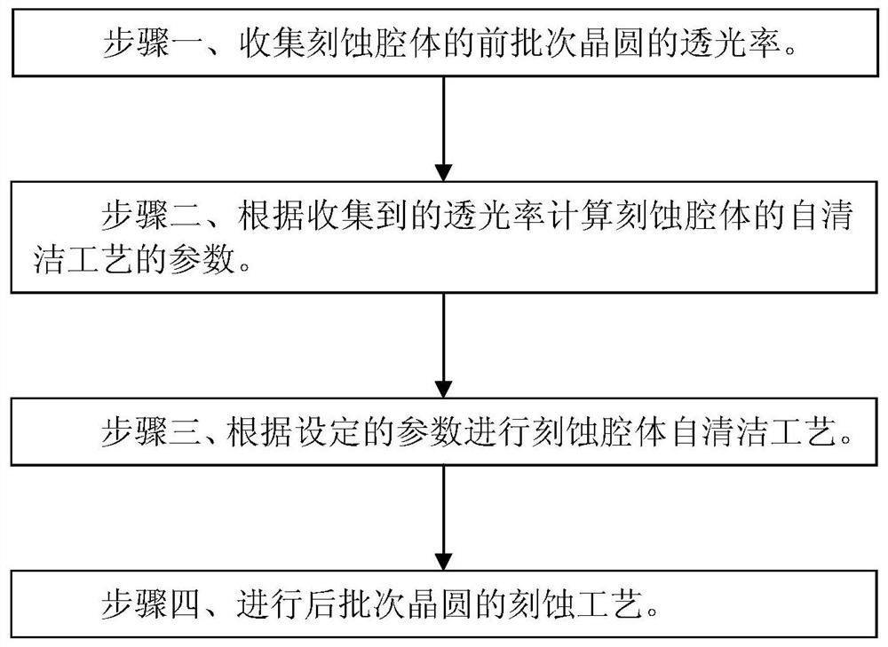
[0038] Such as figure 1 Shown is a flow chart of the polymer cleaning method for etching the cavity according to the embodiment of the present invention; the polymer cleaning method for etching the cavity according to the embodiment of the present invention includes the following steps:

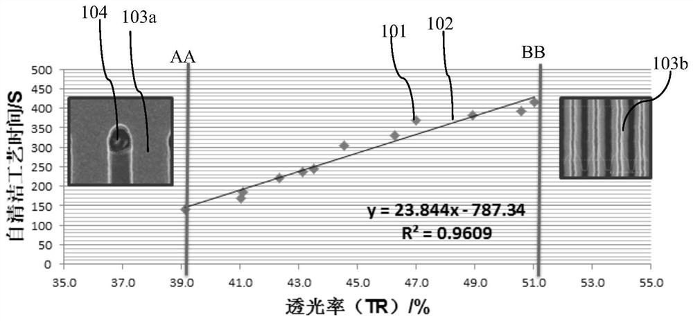
[0039] A step is performed before step 1: establishing a first relational expression and a corresponding first relational curve between the light transmittance of the wafer and the parameters of the self-cleaning process of the etching chamber.

[0040] The etching process of the first batch of wafers corresponding to the method of the embodiment of the present invention is the same as the etching process of the latter batch of wafers. That is, since the same etching process corresponds to the same etching program, the method of the embodiment of the present invention uses the same etching program to etch different batches of wafers.

[0041]The corresponding first relational expression and ...


PUM


Abstract

The invention discloses a polymer cleaning method for etching a cavity, comprising the steps of: step 1, collecting the light transmittance of wafers of previous batches of the etching cavity; step 2, calculating the etching rate according to the collected light transmittance parameters of the self-cleaning process of the etching chamber; step 3, performing the self-cleaning process of the etching chamber according to the set parameters; step 4, performing the etching process of the subsequent batch of wafers. The invention can realize the good cleaning of the polymer in the etching cavity, eliminate the accumulation of the polymer in the etching cavity, thereby eliminating the first chip effect and improving the product yield.

Description

technical field [0001] The invention relates to a semiconductor integrated circuit manufacturing method, in particular to a polymer cleaning method for etching a cavity. Background technique [0002] As integrated circuit technology enters the era of ultra-large-scale integrated circuits, the process size of integrated circuits is developing towards 65nm and smaller structures, and at the same time, higher and more detailed technical requirements are put forward for wafer manufacturing processes. [0003] In the large-scale wafer manufacturing process, dry etching is required. The dry etching process needs to be carried out in the etching chamber. As the number of wafer processing continues to increase, the internal environment of the etching chamber will change accordingly. Changes occur, that is, the previous piece or batch of wafers has a certain degree of influence on the next piece or batch of wafers, which has a memory effect. Wherein, a wafer usually refers to a sili...

Claims


Application Information

Patent Timeline
Patent Type & Authority Patents(China)
IPC IPC(8): H01L21/67
CPCH01L21/67069
Inventor 聂钰节昂开渠吴晓彤江旻唐在峰
Owner SHANGHAI HUALI MICROELECTRONICS CORP
Learn More