Hardware cleaning device

A cleaning device and hardware technology, which are applied in the directions of dry gas arrangement, cleaning method and utensils, cleaning method using liquid, etc., can solve the problems of large production volume of hardware and inconvenience of complete cleaning

Inactive Publication Date: 2018-05-22
ANHUI FANCHANG COUNTY WANNAN VALVE CASTING
View PDF10 Cites 12 Cited by
  • Summary
  • Abstract
  • Description
  • Claims
  • Application Information

AI Technical Summary

Problems solved by technology

[0003] The purpose of the present invention is to solve the problem that the hardware in the prior art is inconvenient to be cleaned in a complete set when the production volume is large, and a hardware cleaning device is proposed.

Method used


Image

  • Hardware cleaning device
  • Hardware cleaning device
  • Hardware cleaning device

Examples


Embodiment 1

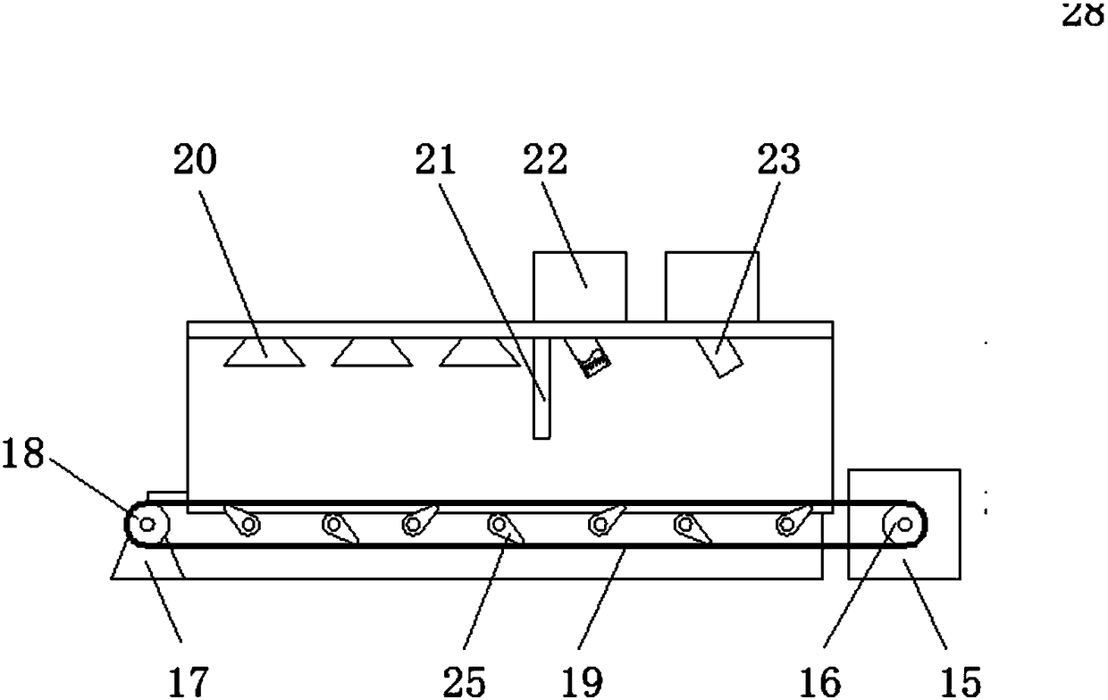
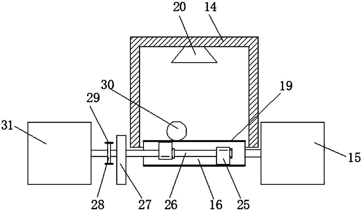
[0019] Embodiment 1: refer to Figure 1-2 , a hardware cleaning device, including a cleaning and drying machine 14, a transmission motor 15 is installed on one side of the bottom of the cleaning and drying machine 14, and a drive roller 16 is installed on the driving end of the transmission motor 15, and the cleaning and drying machine 14 is far away from the transmission One end of motor 15 is provided with mounting frame 17, and rotating shaft is installed on mounting frame 17, and driven roller 18 is sleeved on the rotating shaft, and conveyer belt 19 is wound on drive roller 16 and driven roller 18 jointly, and the upper section of conveyer belt 19 Located inside the cleaning and drying machine 14, the top wall of the cleaning and drying machine 14 is provided with a plurality of water spray ports 20, and one side of the water spray port 20 is equipped with two blowing pipes 23, the blowing pipes 23 and the water spraying ports 20 Partition plate 21 is installed between th...

Embodiment 2

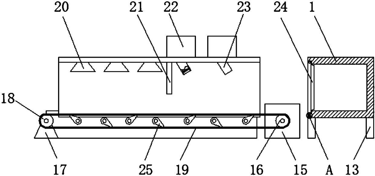
[0020] Embodiment 2: refer to Figure 2-5 , applying the present invention to a heat treatment temperature control device for hardware, comprising a heating furnace 1, a ceramic liner 2 is arranged inside the heating furnace 1, a heater 3 is installed on the lower side of the ceramic liner 2, and the ceramic liner 2 An installation box 4 with openings at both ends is fixedly connected between the outer sidewall and the inner sidewall of the heating furnace 1, and a nitrogen box 5 is installed on the outer sidewall of the ceramic liner 2, and the nitrogen box 5 is located inside the installation box 4, and the nitrogen box 5 The side wall away from the ceramic liner 2 is communicated with a piston cylinder 6, and the inside of the piston cylinder 6 is provided with a piston 7. A pressure sensor 8 is installed on the inner wall of the heating furnace 1, and the probe of the pressure sensor 8 is fixed to the piston 7. connection, the outer wall of the nitrogen box 5 is covered wi...


PUM


Abstract

The invention discloses a hardware cleaning device. The hardware cleaning device comprises a cleaning dryer, a transmission motor is installed on one side of the bottom end of the cleaning dryer, anda drive roll is installed at the driving end of the transmission motor; an installing rack is arranged at the end, far away from the transmission motor, of the cleaning dryer, a rotation shaft is installed on the installing rack and sleeved with a driven roll, the drive roll and the driven roll are jointly provided with a conveyer belt in a winding mode, and the upper section of the conveyer beltis located in the cleaning dryer; and multiple water nozzles are arranged on the top wall of the cleaning dryer, two blowing pipes are installed on one side of the water nozzles, and a partition plateis installed between the blowing pipes and the water nozzles. The hardware cleaning device is simple in structure and easy to implement, the heat treatment quality is improved by cleaning hardware before heat treatment, and therefore the hardware cleaning device is worthy of popularization.

Description

technical field [0001] The invention relates to the technical field of hardware processing, in particular to a hardware cleaning device. Background technique [0002] Hardware refers to tools obtained by processing and casting gold, silver, copper, iron, tin and other metals, which are used to fix things, process things, decorate, etc. Heat treatment refers to a metal thermal processing process in which materials are heated, kept warm and cooled in a solid state to obtain the desired structure and properties. During the progression from the Stone Age to the Bronze and Iron Ages, the role of heat treatment was gradually recognized. Due to the requirements of their working characteristics, hardware such as screws need to be dried and tempered to eliminate excessive internal stress. However, the current heat treatment equipment cannot control the temperature in the heat treatment furnace well. Unstable temperature can easily affect the tempering effect of hardware. Before th...

Claims


Application Information

Patent Timeline
Patent Type & Authority Applications(China)
IPC IPC(8): B08B3/02F26B15/18F26B21/00
CPCB08B3/022F26B15/18F26B21/001
Inventor 沈升好
Owner ANHUI FANCHANG COUNTY WANNAN VALVE CASTING
Why Eureka
Try Eureka