Automatic cooling and cleaning integrated device for machine tool cutting machining process

A cutting processing and automatic cooling technology, which is applied in the direction of positioning devices, metal processing equipment, metal processing machinery parts, etc., can solve the problems of reducing work efficiency, reducing device stability, affecting workpiece cutting, etc., achieving reasonable design and improving cooling effect , increasing the effect of stability

Inactive Publication Date: 2018-05-22
李京帅
View PDF8 Cites 6 Cited by
  • Summary
  • Abstract
  • Description
  • Claims
  • Application Information

AI Technical Summary

Problems solved by technology

[0004] Publication No. CN 107000149 A discloses a cutting device, the main purpose of which is to prevent the coolant from being directly sprayed onto the tip of the tool and to protect the driveway, but it is also inconvenient to adjust the cooling rate according to the rotational speed of the workpiece when spraying the coolant. Spraying the coolant makes it inconvenient to use the coolant reasonably, and it is impossible to protect the turning tool and the workpiece. It is easy to overheat the cutting part of the workpiece and cause damage to the workpiece. There are also devices that spray the coolant on the workpiece manually. Continuous spraying reduces work efficiency, and some devices need to pull the catheter tube repeatedly when spraying coolant on the surface of the workpiece, so that it is inconvenient for the coolant outlet tube to move with the turning tool, and it is inconvenient to follow When some devices are in use, when the workpiece is tightened and fixed, it is inconvenient to stably fix rod-shaped workpieces of different lengths, which reduces the stability of the device. , the workbench needs to be cleaned manually, which is laborious. At the same time, cutting debris is easy to adhere to the surface of the workpiece, which affects the cutting of the workpiece, and it is inconvenient to remove dust on the surface of the workpiece during the cutting process.

Method used


Image

  • Automatic cooling and cleaning integrated device for machine tool cutting machining process
  • Automatic cooling and cleaning integrated device for machine tool cutting machining process
  • Automatic cooling and cleaning integrated device for machine tool cutting machining process

Examples


Embodiment Construction

[0022] The following will clearly and completely describe the technical solutions in the embodiments of the present invention with reference to the accompanying drawings in the embodiments of the present invention. Obviously, the described embodiments are only some, not all, embodiments of the present invention. Based on the embodiments of the present invention, all other embodiments obtained by persons of ordinary skill in the art without making creative efforts belong to the protection scope of the present invention.

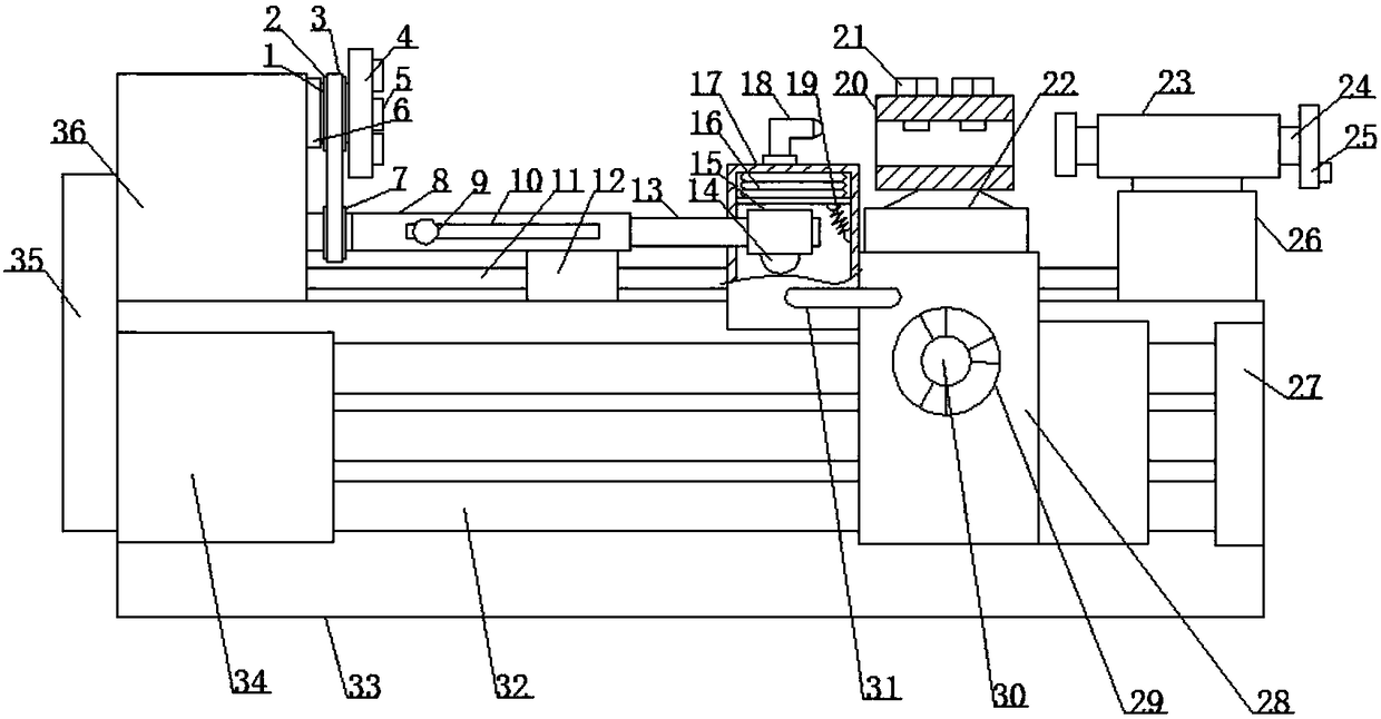
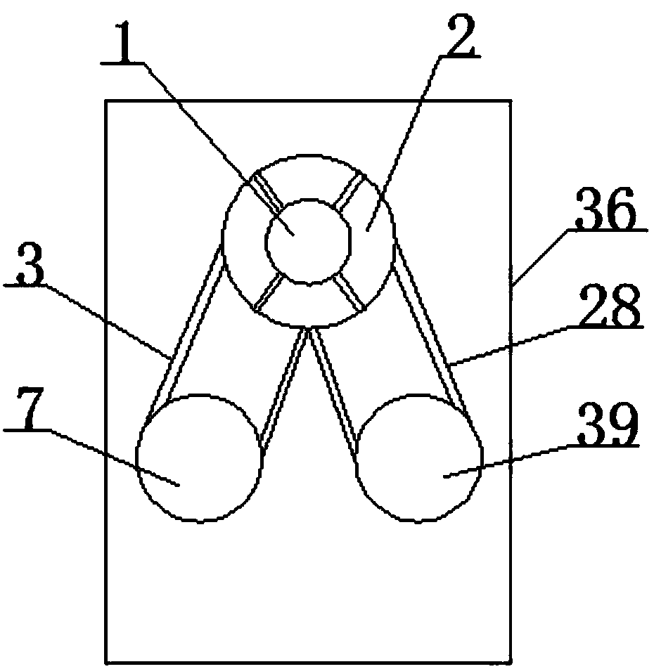
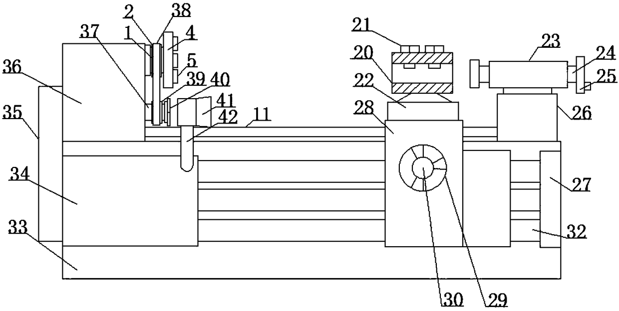
[0023] see Figure 1-3 , the present invention provides a technical solution:

[0024] An automatic cooling and cleaning integrated device for the cutting process of a machine tool, including a machine table 33, a positioning plate 27 is fixedly installed on the front right end of the machine table 33, a feed box 34 is fixedly installed on the front left end of the machine table 33, and the feed box 34 is fixedly installed on the front left end of the machine ...


PUM


Abstract

The invention aims to solve the problem that an existing machine tool cannot conveniently spray cooling liquid along with the rotation speed of workpieces, and discloses an automatic cooling and cleaning integrated device for the machine tool cutting machining process. The automatic cooling and cleaning integrated device comprises a first rotary shaft, a first rotary wheel, a first belt, a chuck,a gripper, a sleeve ring, a second rotary wheel, a sleeve pipe, a slide block, a guide groove, a guide rod, a supporting block, a slide rod, a push block, a connection block, a telescopic airbag, a connection box, a discharging pipe, a spiral spring, a knife rest, fastening screws, a supporting table, a guide pipe, a positioning rod, a first rotary disc, a positioning table, a positioning plate, asliding box, a second rotary disc, a first screw rod, a connection rod, second screw rods, a machine table, a feeding box, a connection plate, a spindle box, a second rotary shaft, a second belt, a third rotary wheel, a fan, an air guide cover and a supporting rod. According to the automatic cooling and cleaning integrated device, the sleeve pipe is driven by the second rotary wheel to rotate, accordingly, cooling liquid is sprayed out through the discharging pipe, the cooling liquid can be conveniently sprayed onto the surface of a workpiece automatically in the machine table operation process, and the workpiece is cooled.

Description

technical field [0001] The invention relates to the field of machine tool cutting, in particular to an automatic cooling and cleaning integrated device for the machine tool cutting process. Background technique [0002] Any cutting process must have three basic conditions: cutting tool, workpiece and cutting motion. Cutting tools should have cutting edges whose material must be harder than the workpiece. Different tool structures and cutting motion forms constitute different cutting methods. The methods of cutting with a tool with a fixed blade shape and the number of blades include turning, drilling, boring, milling, planing, broaching, and sawing; Cutting methods include grinding, lapping, honing and polishing. [0003] Cutting is the most important processing method in mechanical manufacturing. Although the manufacturing precision of rough blanks has been continuously improved, and processing technologies such as precision casting, precision forging, extrusion, and po...

Claims


Application Information

Patent Timeline
Patent Type & Authority Applications(China)
IPC IPC(8): B23Q11/00B23Q11/10B23Q3/06
CPCB23Q11/00B23Q3/06B23Q11/10
Inventor 李京帅
Owner 李京帅
Why Eureka
Try Eureka